Hello Azm
Here is the topology that you described.
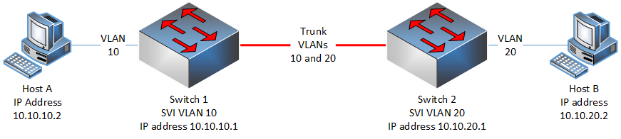
Except for the labeling in the diagram, the network has the following elements:
- VLAN 10 subnet is 10.10.10.0/24
- Host A has a default gateway of 10.10.10.1
- VLAN 20 subnet is 10.10.20.0/24
- Host B has a default gateway of 10.10.20.1
- Both Switch 1 and Switch 2 are layer 3 switches
- We assume that no additional SVIs or routed ports are configured on either switch.
Keep in mind that the order of operations of MAC address-table lookup and routing is based on the order in which encapsulation and de-encapsulation take place.
Let’s go through it step by step. If Host A sends a packet to 10.10.20.2, it will
- Encapsulate the packet at the Network layer (layer 3) with a destination IP address of 10.10.20.2.
- To encapsulate the Data link layer (layer 2), it has to find the destination MAC address. Because the destination IP address is in a different subnet, and because MAC addresses only have significance within the current subnet, Host A will place the MAC address of the local default gateway (which is the SVI on Switch 1) into the destination MAC address field. If Host A does not know this MAC address it will send an ARP request for the 10.10.10.1 address. The SVI of Switch 1 will respond with its MAC address.
- The frame is placed on the medium and sent to Switch 1
- The switch receives the frame, de-encapsulates it and determines the destination MAC address to be that of its SVI. It continues to de-encapsulate and determines that the destination IP address is 10.10.20.2. It then looks at the routing table and sees no route for this destination and it drops the packet.
The hosts will not be able to talk to each other.
Routing in its simplest form is just the process by which a layer 3 device chooses the egress port through which to send a packet based on its destination address. This means that in order for routing to take place, there must be at least two layer 3 ports (virtual or not) on a device - one to be the incoming port and one to be the outgoing port.
The above topology has both layer 3 switches with only one layer 3 port each - the SVI port. So all packets that arrive at the SVI port to be routed will be dropped. The best and most straightforward way to allow the above topology to work is to choose one of the two switches to perform inter-VLAN routing, and configure both SVI ports (VLAN 10 and 20) on that switch providing for both an ingress port and egress port. Just make sure that the default gateways are configured correctly on the hosts as well.
I hope this has been helpful!
Laz