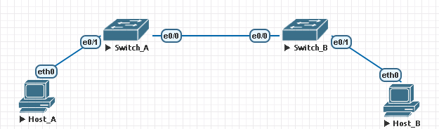
Host_A IP - 10.10.10.1/24
Host_B IP - 10.10.10.5/24
Now these two hosts can communicate with each other successfully. But I don’t get the theory behind how this works. So can you explain the each step from the beginning where Host_A sends the ARP request to find the MAC address of the Host_B, how that frame handle by switches, how Native VLAN plays it part here, etc..?
Host_A (10.10.10.1) pings Host_B (10.10.10.5). Assuming that it doesn’t know Host_B’s MAC address, it will generate an ARP broadcast request frame and begin looking for it. The frame simply says “Host_B (10.10.10.5), what is your MAC address?”
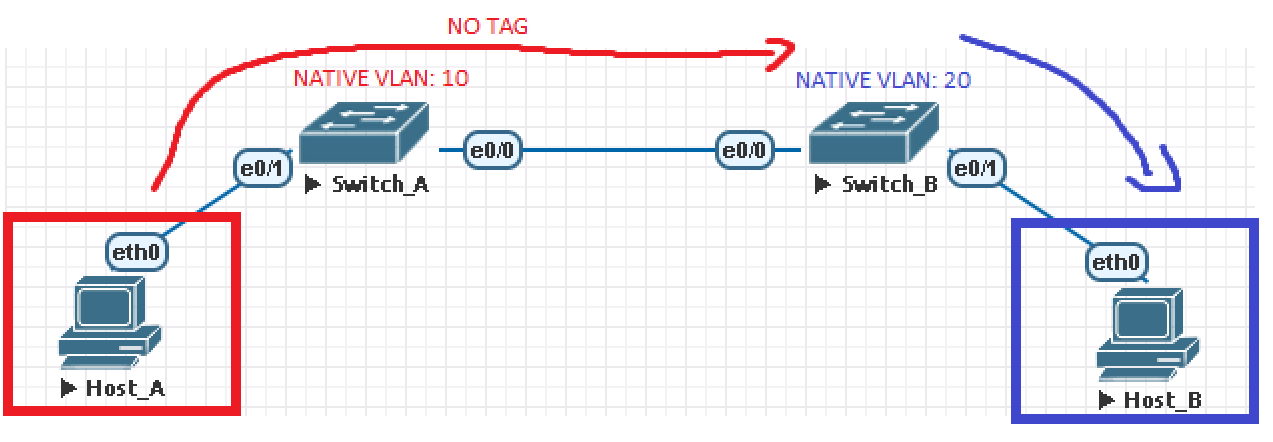
Switch_A receives the ARP frame on its E0/1 interface that is assigned to VLAN 10. It will flood the broadcast frame out of all ports that are associated with VLAN 10 (apart from the port where it received this frame on) which also includes the e0/0 trunk port since it carries VLAN 10 data.
The ARP frame is sourced from VLAN 10 and VLAN 10 is configured as the native/untagged VLAN on the trunk port. This means that Switch_A will send the frame over the trunk untagged.
Switch_B receives this frame and notices that it has no tag. Switch_B therefore assumes that it’s part of its configured native/untagged VLAN which is VLAN 20 and it will flood it out of all ports (except the one where the frame was received on) that are associated with VLAN 20 which includes E0/1 where Host_B resides.
Host_B receives the frame, processes it, and generates an ARP reply. The ARP reply is sent as unicast towards Host_A’s MAC address since Host_B has Host_A’s MAC from the original ARP request.
Switch_B receives the frame from Host_B on its e0/1 interface. It notices that this interface is associated with VLAN 20. The native VLAN configured on its trunk port e0/0 is also 20, so it therefore sends the frame over the trunk link as untagged
Switch_A receives this frame and notices that its untagged and assumes that the traffic is part of VLAN 10 because VLAN 10 is configured on it as the native/untagged VLAN. It therefore sends the frame to Host_A (which resides in VLAN 10)
Any further packets will now take the same direction and flow the same way.
Because of the native VLAN mismatch, the hosts can still communicate because the switches don’t really know which VLAN is the traffic coming from. If its untagged, they just assume its coming from the native VLAN which can create a problem if both switches have a different native VLAN configured. This way, the devices can talk even without passing a routing device at first, if they reside on the same IP network.
Switch_B receives untagged frames from Switch_A and thinks that they belong to VLAN 20 because VLAN 20 is configured on Switch_B as the native/untagged VLAN.
Switch_A receives untagged frames from Switch_B and thinks that they belong to VLAN 10 because VLAN 10 is configured on Switch_A as the native/untagged VLAN.
The best practice is to ensure that the native VLAN configuration is the same on both switches to prevent problems like this occuring from the future. Depending on the configuration, certain traffic could also end up being blackholed if the native VLAN has a mismatch.