Hi Rene,
Could you please explain Jumbo Frame in plain English ![]()
who uses it and why someone will use it ? Is it configurable ? Where this has to be configured ?
Regards
Abhishek
Hi Rene,
Could you please explain Jumbo Frame in plain English ![]()
who uses it and why someone will use it ? Is it configurable ? Where this has to be configured ?
Regards
Abhishek
Hello Abhishek
In order to clearly answer your question, you’ll have to understand the following terminology:
MTU - Maximum transmission unit - this is the largest physical packet size measured in bytes that a network can transmit. Any packet larger than this MTU is divided or fragmented into smaller packets before transmission. The standard MTU on an Ethernet network is 1500 bytes plus the size of the L2 header and frame check sequence which is an additional 18 bytes. So standard MTU size for Ethernet is 1518.
Jumbo frame - A frame that is larger than the standard MTU size of 1518 bytes. This definition is vendor dependant and is not part of any IEEE standard. For Cisco, 1518 or 1522 in the case of Q in Q is the standard MTU. Anything larger is considered a jumbo frame.
When encapsulation from Layer 2 to Layer 3 occurs, if you have a frame that is say, 1600 bytes in size, in order for it to be encapsulated to layer 3, if there is an MTU setting of 1518, this frame will be fragmented into two parts, and each part will be placed in a separate packet. So one frame can be fragmented into two (or more) packets when encapsulated.
A network can be configured to accommodate jumbo frames, that is on layer 2, frames of sizes up to 9216 bytes for Gigabit Ethernet and faster interfaces can be used. 10/100Mbps ports are limited to 8092 bytes. MTU is configured on interfaces, such as physical interfaces of a switch or router, or on SVIs. Some platforms have a global MTU size configuration parameter. If all interfaces on all devices within a flat layer 2 network are configured to accommodate jumbo frames, this could be very useful especially when configuring the core or backbone of a network. Large bulks of data can be sent in this manner with much less overhead.
When using jumbo frames, it is important to be sure that the design you create is sound. If there is routing involved, that is if these large frames are going up to layer 3, then fragmentation of these frames may occur and this can easily slow down a network or even drop frames that cannot be fragmented.
I hope this has been helpful!
Laz
19 posts were merged into an existing topic: 802.1Q Tunneling (Q-in-Q) Configuration Example
Hi there,
For Q-in-Q, are you using real hardware cisco switches or a Virtual (GNS3, Unetlab, VIRL, etc), I’m just curious coz IOU switches seems not supported Q-in-Q.
thanks
Gerard
Hello Gerard
The Q-in-Q configurations that I have configured are on real production equipment. I haven’t tried configuring it on a virtual lab. Having said that I know that GNS3 does not fully emmulate switches. GNS3 documentation indicates that GNS3 switches will only support VLANs with 802.1q trunking. Anything beyond that, such as pruning is either difficult to get working or not supported altogether. However, some people have claimed to get it to work with the generic switches on GNS3. Take a look at this GNS3 forum link: http://forum.gns3.net/topic6100.html
Similarly, IOU switches don’t run the full IOS but a subset. You may be able to run more IOS instances on IOU than GNS3, but GNS3 can run the real IOS version. As far as I can see from the research I did, IOU will not run Q-in-Q. I believe you can configure it but it will not function.
I hope this has been helpful!
Laz
Dear Rene,
I have two 802.1Q tunneling (Q-in-Q) links from different service providers connect between two sites.
We are planing to use active - active connection for those links. Do we need to configure ether channel or not?
Are there any other guidance not only ether-channel, please teach?
Hello Sannlynntun
One option would definitely be the use of etherchannel. It would provide for the best and most efficient use of the bandwidth that is available for both links. Another option would be to configure STP such that some of your VLANs use the one link and the rest use the other link. If one goes down, STP will re-converge and send all your VLANs over the active link. This may not be as granular or as efficient as etherchannel, but depending on your needs it may suffice.
In either case, the fact that you are using QinQ doesn’t affect what solution you will use. From your perspective, you just have two trunks that connect your two sites. The ISP is doing all the QinQ stuff.
I hope this has been helpful!
Laz
Hello guys,
I just would like to know what IOS you are using for this lab? I’m currently using Fast Ethernet ports to create the sub interfaces and it’s not working. I am new to this site and I find it almost impossible to start a question by itself.
Hello @danietec06,
For the switches I used some 3560s using IOS 12.2(55):
SW1#show version
Cisco IOS Software, C3560 Software (C3560-IPSERVICESK9-M), Version 12.2(55)SE10, RELEASE SOFTWARE (fc2)
Technical Support: http://www.cisco.com/techsupport
Copyright (c) 1986-2015 by Cisco Systems, Inc.
Compiled Wed 11-Feb-15 11:34 by prod_rel_team
Image text-base: 0x01000000, data-base: 0x02F00000

ROM: Bootstrap program is C3560 boot loader
BOOTLDR: C3560 Boot Loader (C3560-HBOOT-M) Version 12.2(44)SE5, RELEASE SOFTWARE (fc1)

SW1 uptime is 1 minute
System returned to ROM by power-on
System image file is "flash:/c3560-ipservicesk9-mz.122-55.SE10.bin"
The routers that I used as client devices are 2811s:
R1#show version
Cisco IOS Software, 2800 Software (C2800NM-ADVENTERPRISEK9-M), Version 15.1(4)M10, RELEASE SOFTWARE (fc2)
Technical Support: http://www.cisco.com/techsupport
Copyright (c) 1986-2015 by Cisco Systems, Inc.
Compiled Tue 24-Mar-15 09:00 by prod_rel_team

ROM: System Bootstrap, Version 12.4(13r)T, RELEASE SOFTWARE (fc1)

R1 uptime is 1 minute
System returned to ROM by power-on
System image file is "flash:c2800nm-adventerprisek9-mz.151-4.M10.bin"
What device did you try to create sub-interfaces on? You can only do this on routers, not on switches.
Rene
Hello there
I have a question about Q-in-Q implementation. See the lesson showed typical example, that configure dot1q-tunnel at the PE Ingress port, adding the outer tag, then remove it at the remote PE. What if the PE1 ingress port(f0/1 in the class TOP) is a L3 port, so cannot use the command " sw mod dot1q-tunnel" at the ingress port, but still can add dot1q encap. Is there a way to still setup the dot1q-tunnel at the PE1 egress port, meaning adding the outer tag at the PE1 egress port(f0/19 in the class TOP) ?
Or, what if the PE1 ingress port(f0/1 in the class TOP) is a Trunk port and already have some vlans running on it. any way still pick out one(or some) VLAN IDs in the Trunk port to do Q-in-Q, add the outer TAG then send out?
I think my ultimate question is: Does the ingress port of the device(whereever the Q-in-Q tunnel starts) have to be a switch access port?
Hello Bayonet
802.1Q-in-Q is an exclusively layer 2 feature. It cannot be applied to a layer 3 port. The encapsulation dot1q command on a layer 3 port is used in order to configure Router on a Stick and cannot be used to configure QinQ.
I hope this has been helpful!
Laz
Hello again Bayonet
When configuring Q-in-Q it is necessary to configure the link between the “customer” device and the “telco” device as an asymmetric link. That means that the customer end is configured as an 802.1Q trunk port and the telco end is configured as a tunnel port. The tunnel port is always configured as an access port with a specific VLAN ID as well as with the command switchport mode dot1q-tunnel that makes it a tunnel. This end cannot be configured as a trunk port.
I hope this has been helpful!
Laz
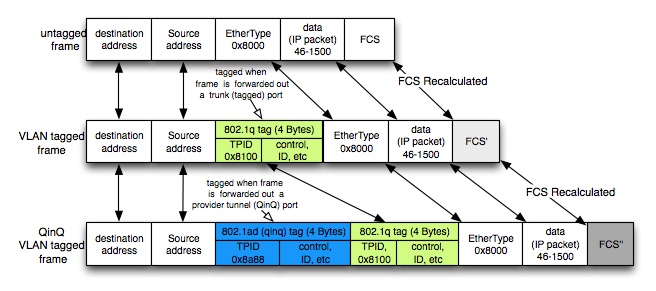
Hi Rene, Inside the SP network the outer tag is blue (frame b/w SP switches). I believe that outer tag should be green, inner tag should be blue (see http://1.bp.blogspot.com/-IMVq7Bmx8OQ/TezgU7Gwr5I/AAAAAAAAAIg/Zu_8Bo2Oe1g/s1600/qinq1.jpg) because outer tag is svlan. Inner tag is cvlan. Do I miss something?
Thanks.
Adrian
Hello Adrian
Looking over the lesson, I believe that you are correct. Thanks for catching that! The inner tag should be blue and the OUTER tag (on the left of the blue tag) should be green.
I will let @ReneMolenaar know about this to make the appropriate changes.
Thanks again!
Laz
Hi Laz,
You are very welcome. Thank you too!
Adrian
You are right Adrian, thanks for notifying us. I just fixed it.
Hi Lagapides
Are customers with multiple tags transported or just all customers use only one VLAN?
Hi Samit,
Typically, the SP will use a different VLAN ID for each customer. When you have two customers, you could use VLAN 10 for customer A and VLAN 20 for customer B.
Rene
A post was merged into an existing topic: EtherChannel over 802.1Q Tunneling