Hello Mr. René Molenaar; thank you already for the course and I announce in passing that I have validated my CCNP 350-401 indeed I am doing revisions for the purpose of a job interview but also in order to prepare the ENARSI 300- 410 . my concern is this why can 802.1Q be tunneled and in what context is it advisable to think of this technology instead of the other (please enlighten me on a similar technology)? because you can ask me…
Bonjour monsieur René Molenaar ; merci déjà pour le cours et je vous annonce en passant que j’ai validé mon CCNP 350-401
en effet je suis entrain de faire des révision dans le but d’un entretien d’embauche mais aussi afin de préparer le ENARSI 300-410 . ma préoccupation est celle-ci pourquoi déployer le tunnelisation 802.1Q et dans quel contexte c’est conseillé de penser à cette technologie au lieu de l’autre ( veillez m’éclairer sur une technologie similaire ) ? parce que l’on pourra me poser la question de pourquoi j’aurai opté ça au lieu de l’autre , j’espère que ma question est compréhensive ? merci d’avance
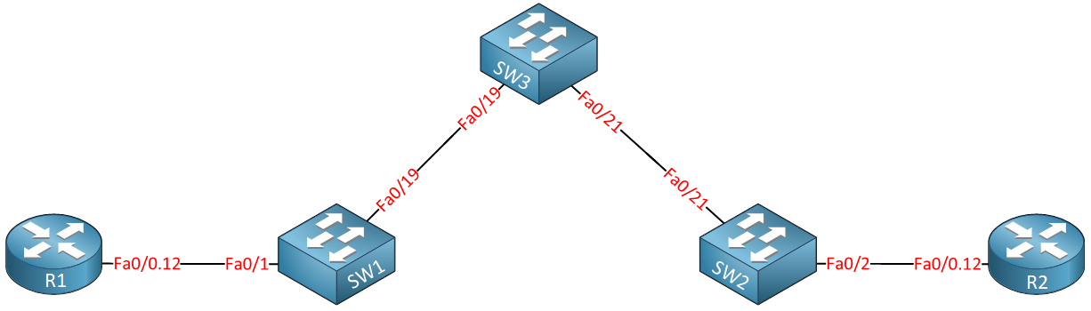
The traffic that is sent from R1 reaches R2 on layer 2. From end to end, this is a Layer 2 connection, and thus no routing is involved.
I believe you are asking if within the ISP’s infrastructure, if you can have any routing, say between SW1, SW2, and SW3. What if that infrastructure is composed of dozens or hundreds of routers? Then it would make sense that the QinQ tunnel can be transmitted over a routed underlay infrastructure.
The answer is yes, you can do this, and you will find that ISPs will indeed have a Layer 3 underlay that carries Layer 2 traffic that goes end to end, much like QinQ does.
How would you do this? Well there are several ways. MPLS is one type of underlay network that can carry multiple types of data. Here’s a lesson that explains this further:
Alternatively, you can use L2TP to tunnel layer 2 over a Layer 3 network. This NetworkLessons note has more info on this protocol.
Another option is to use L2VPN or VPLS, again, more about which you can learn at this NetworkLessons note.
Keep in mind that all of these options are not limited to being used with QinQ, but are able to transport all types of Layer 2 traffic over a Layer 3 Underlay network.
Congratulations for passing the ENCOR 350-401 course, that’s a great accomplishment! I hope we can continue to help you along the way for both your ENARSI 300-410 and your job interviews.
Concerning your question, QinQ is typically used by a telco when delivering Metro Ethernet at Layer 2. It is ideal when your customers have multiple VLANs that they want to share among their multiple buildings. By tunneling all of the VLANs of the customer through a single VLAN on the telco infrastructure, you don’t have to worry about duplicate or interfering VLAN IDs between the customer and the telco, or between multiple customers.
A very practical example I can give you is one with which I have worked. In the city I live in, a municipal fiber optic network was deployed about ten years ago that is used to interconnect all public services. The municipality has about 12 buildings throughout the city that are consolidated into a single network with various VLANs (voice data and others) used across all sites. The fiber optic network, with Cisco devices at all the nodes, uses QinQ to keep all of the VLANs of the municipality tunneled on VLAN 35. Similarly, hospitals, schools, and other entities each have their own VLAN on the fiber optic network through which they tunnel all of their VLANs. That way you keep each customer separate while delivering Layer 2 connectivity to them.
First of all, I think the command you’re looking for is l2protocol-tunnel cdp. This command will cause an interface to encapsulate any received CDP messages within the QinQ tunnel. In other words, it won’t receive them and process them as if the interface itself is the intended destination, but it will encapsulate them and tunnel them through without processing them as CDP messages.
If you configure the no cdp enable command on that same interface, it will not cause any conflict in operation. This command tells the interface not to participate in any CDP communication. So it won’t generate any CDP messages, and it won’t process any messages it may receive.
If CDP messages are tunneled, then it won’t process any CDP messages anyway since all received CDP messages are encapsulated in the tunnel and sent along their way.
So these two commands are not incompatible. Looking at the lesson, the no cdp enable command was not actually used anywhere. Where did you encounter it?
You can find out more info about how to tunnel CDP and other Layer 2 protocols in such a scenario, take a look at this Cisco command reference:
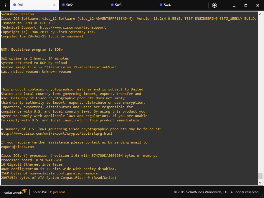
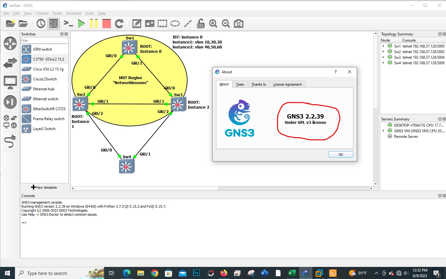
I have tried the lab in GNS3, and everything seemed to work just fine until I get to verify the dot1q tunnel on the switches. Then it won’t accept the command show dot1q-tunnel; the only command that’s available is show dot1x. My question is, what switches have you used in this lab? Can I use the same switch in GN3? If not, how can I do it without having the physical switch?
Thank you so much.
Typically, Rene uses Cisco Modeling Labs (CML), and in the past used Cisco VIRL for the practical parts of the labs. In particular, the currently available virtual switch version is:
Can you share with us your particular platform and IOS version that you are attempting this configuration on? Does your platform support the rest of the commands in this lesson? I find it interesting that Q-in-Q is supported, but this specific command is not. Let us know more so that we can further advise you on how to proceed to get the most out of the equipment you have available.
I’m surprised that your setup doesn’t allow for the show dot1q-tunnel command. I would have thought that it would be available on almost all images and under all implementations because it is a very basic functionality. In any case, I can’t answer why it’s not available in your particular setup.
Now concerning VIRL and CML images, both VIRL and CML use the same type of virtual machine images to emulate various Cisco operating systems for network simulation. So at a fundamental level, the images used by VIRL and CML do not differ significantly.
However, there might be differences in terms of the specific versions of images that are supported by each platform. CML, being the newer platform, might support newer image versions or have better optimization for certain images. It’s also possible that some older VIRL images may not be compatible with CML, especially if they’ve been deprecated in the newer platform.
However, I don’t believe that the use of VIRL or CML should have an impact on such a basic functionality and command set as those for Q-in-Q. So I don’t believe that the problem here has to do with the use of CML or VIRL images. I’m sorry that I could not have been of more help for you!
Cisco includes a disclaimer with their exam blueprints that always leaves a window open for them to add related technologies and information. In the Infrastructure - Layer 2 section (3.1) I could see them including something about 802.1Q Tunneling.
So although it is not explicitly stated in the blueprint, there is a good possibility that it may come up.
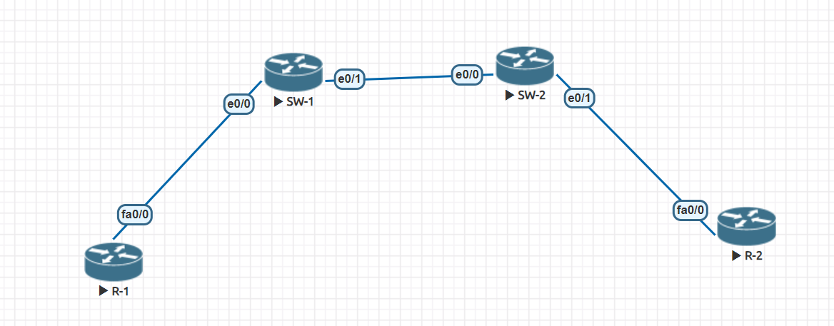
i have replicated the same toplogy what Mr.Rene did, but for its not working. I am unable have L3 reachability b/w R1 and R2. please refer to the attached configurations for R1,R2 and Sw1/SW2 . Please check and advise to in order to get reachability
Routers : 7200 model
Switch : IOL image
R1:-
Router#sh ip int brie | ex unas
Interface                  IP-Address      OK? Method Status                Protocol
FastEthernet0/0.12         192.168.12.1    YES manual up                    up

Router#sh run int FastEthernet0/0.12
Building configuration...

Current configuration : 99 bytes
!
interface FastEthernet0/0.12
 encapsulation dot1Q 12
 ip address 192.168.12.1 255.255.255.0
end

Router#
SW1:-
SW1#show vlan id 123

VLAN Name                             Status    Ports
---- -------------------------------- --------- -------------------------------
123  VLAN0123                         active    Et0/0, Et0/1

VLAN Type  SAID       MTU   Parent RingNo BridgeNo Stp  BrdgMode Trans1 Trans2
---- ----- ---------- ----- ------ ------ -------- ---- -------- ------ ------
123  enet  100123     1500  -      -      -        -    -        0      0

Primary Secondary Type              Ports
------- --------- ----------------- ------------------------------------------

SW1#sh run int e0/0
Building configuration...

Current configuration : 100 bytes
!
interface Ethernet0/0
 switchport access vlan 123
 switchport mode dot1q-tunnel
 duplex auto
end

SW1#sh run int e0/1
Building configuration...

Current configuration : 103 bytes
!
interface Ethernet0/1
 switchport trunk encapsulation dot1q
 switchport mode trunk
 duplex auto
end

SW1#
SW2:-
SW2#show vlan id 123

VLAN Name                             Status    Ports
---- -------------------------------- --------- -------------------------------
123  VLAN0123                         active    Et0/0, Et0/1

VLAN Type  SAID       MTU   Parent RingNo BridgeNo Stp  BrdgMode Trans1 Trans2
---- ----- ---------- ----- ------ ------ -------- ---- -------- ------ ------
123  enet  100123     1500  -      -      -        -    -        0      0

Primary Secondary Type              Ports
------- --------- ----------------- ------------------------------------------

SW2#sh run int e0/0
Building configuration...

Current configuration : 103 bytes
!
interface Ethernet0/0
 switchport trunk encapsulation dot1q
 switchport mode trunk
 duplex auto
end

SW2#sh run int e0/1
Building configuration...

Current configuration : 100 bytes
!
interface Ethernet0/1
 switchport access vlan 123
 switchport mode dot1q-tunnel
 duplex auto
end

SW2#
R2:-
Router#sh ip int brief  | ex unas
Interface                  IP-Address      OK? Method Status                Protocol
FastEthernet0/0.12         192.168.12.2    YES manual up                    up

Router#sh run int fa0/0.12
Building configuration...

Current configuration : 99 bytes
!
interface FastEthernet0/0.12
 encapsulation dot1Q 12
 ip address 192.168.12.2 255.255.255.0
end

Router#
Looking at your configs everything looks like it should be working. I don’t see anything wrong. However, you can attempt to determine the state of the QinQ tunnel by using some of the verification commands included in the lesson such as:
SW1#show dot1q-tunnel on both switches
SW1#show interfaces trunk also on both switches to see what trunks have been configured and allowed
If you can also do a wireshark capture of the packets as they arrive on the switch to see their size and what kind of VLAN ID you see in the Ethernet frame, just to ensure that you get the expected results.
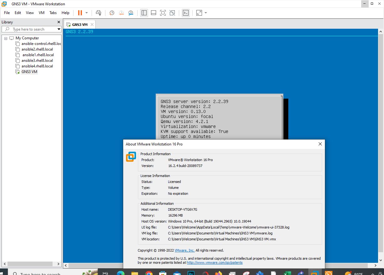
Finally, if you’re using GNS3, it may just be a problem with the images. Take a look at this GNS3 post: https://gns3.com/getting-qinq-working-on-gns3
I don’t know if this has been resolved since this post (which is almost 4 years old) but it’s worth looking into.
SW1#show dot1q-tunnel on both switches ==== >> Switch doesn’t support this command . SW1#show interfaces trunk also on both switches to see what trunks have been configured and allowed ===== >> Outter vlan 123 shows on both switches of trunk port .
apart from these i dont see any verification command.
i simulated this lab in Eve-ng. Can you suggest any image that could support 802.1Q tunnel.