BGP Route Reflector

Hello Duong

Can you clarify what it is that you are requesting? Can you give us a little more information about the architecture you are trying to create and for what purpose?

Also keep in mind that if you have a suggestion for a lesson, you can always go to the Member Ideas page shown below, and make a suggestion for a particular lesson you’d like to see. You may find that others have made similar suggestions and you can add your voice to theirs.

In the meantime, take a look at this Cisco documentation that describes BGP route reflectors and how they can be incorporated into an ACI Fabric in a data center.

I hope this has been helpful!

Laz

we need lap leaf-spine topology with 2 router reflectors

Hello Duong

I forgot to add the link to the Member Ideas page. Here it is:

You can make your suggestion there, and Rene will take a look…

I hope this has been helpful!

Laz

Hello,

In the last example if all the router in each cluster are connected with each other with IGP would that causes any problem ?

Thank you

Hello Chansaravuth

I believe you are talking about this topology, correct?

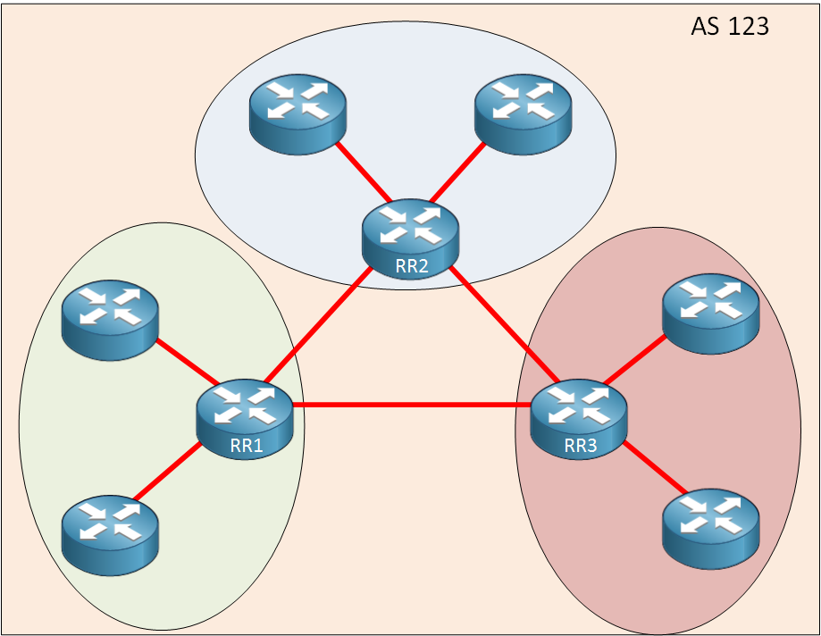
As with any BGP AS, all routers within an AS must be reachable in order for BGP to function correctly. Whether you use an RR or not, all routers within AS 123 must have routing established between them. This is typically achieved using an IGP like OSPF or EIGRP. So yes, an IGP should run in the AS to ensure reachability between all routers.

I hope this has been helpful!

Laz

This only is for routes correct? It wouldnt reflect things like the update-source command or next-hop-self correct?

Hello Cameron.

Correct. The next-hop is not changed as the route reflector reflects the update. It’s basically like a mirror. Consider this topology:

R1, R2 and R3 each have networks that correspond to their router number, for ex:
R1 - 10.10.10.10/32
R2 - 20.20.20.20/32
R3 - 30.30.30.30/32

R4 is configured as a route reflector. When R1 advertises its network to R4, R4 will reflect it and the message will look something like this:

BEFORE BEING REFLECTED

AFTER BEING REFLECTED (packet captured from R4 to R3)

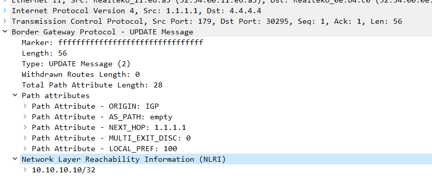
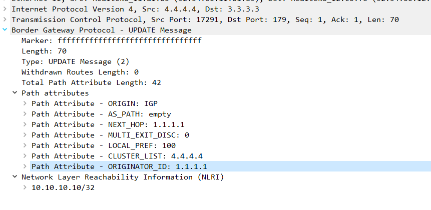
Notice how the next-hop wasn’t changed, it still refers to R1. What has changed was the addition of two new path attributes - Cluster List and Originator ID that Rene covers in his lesson.

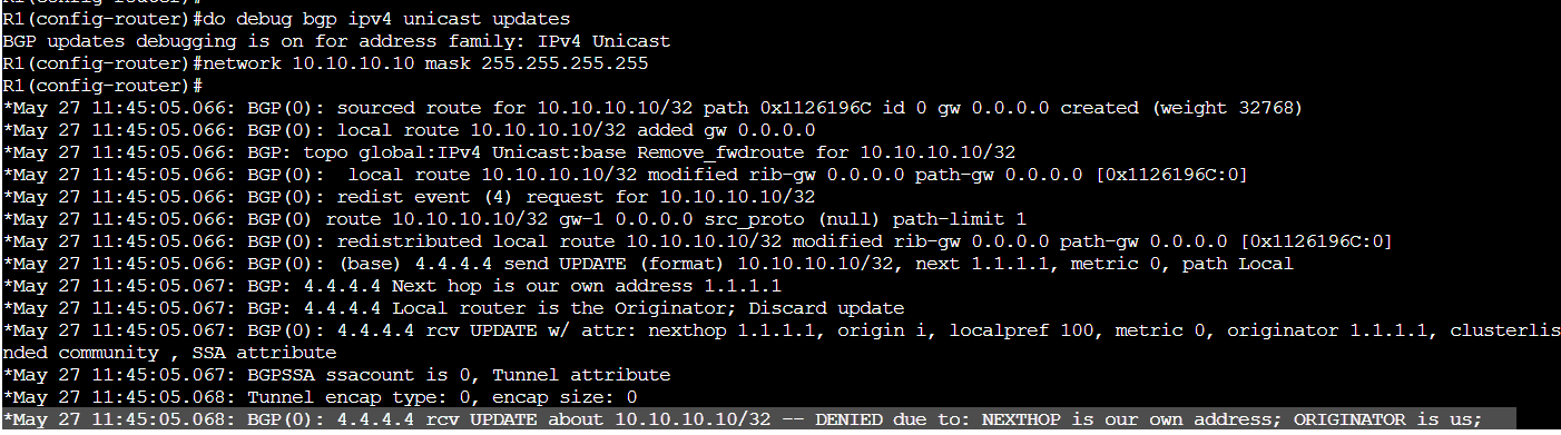
The originator_ID is the router ID of the router from who the route originates from. It’s used as a loop prevention mechanism. If the router sees its own RID here, it will discard the packet.


(When the reflector reflects the update, it also reflects it back to the originator so you get to nicely capture this in action)

If you have any further questions, feel free to ask.

David

1 Like

Hello Cameron

Yes, route reflectors will only reflect routes. Configurations like update-source and next-hop-self are functions that operate within the confines of the router on which they are configured.

I hope this has been helpful!

Laz

My understanding is for RRs, if one Router in a Cluster gets a “no-advertise” community, it will not advertise those routes to other RRs in the cluster.

Are there any techniques to allow for that?

The only thing I can think of is set your own internal community and filter appropriately on inbound / outbound Route Maps.

Hello Andrew

Yes, you’re right. In a BGP RR cluster, if an RR or even one of its clients receives a route with the “no-advertise” community, it will not advertise this route to any other BGP peer, including an RR, or RR clients within the cluster.

To overcome this, you can indeed use your own internal community and filter accordingly using inbound or outbound Route Maps. This way, you can manipulate the route advertisements as per your requirements.

Here’s a brief example of how you can do this:

  • Remove the “no-advertise” community from the received routes.
  • Set your own community.
  • On the outbound direction, match your community and set the “no-advertise” community back again if needed.

You are the master of your own domain (i.e. your own AS) so you can manipulate the communities as you see fit. Remember to apply these configurations on routers in the cluster to ensure consistency, otherwise, it can lead to routing loops or suboptimal routing.

I hope this has been helpful!

Laz

Do you have a sample setup with multiple route-reflectors within an AS?

I’d like to know how to configure the RR’s in such an environment.

Hello Roger

At this time, we don’t have a lesson with multiple RRs. However, on Rene’s GNS3 Vault site, he does have a lab with two RRs. You can find it here:

You can use this as a base from which you can experiment with multiple RRs. In the meantime, you can also make a suggestion for a new lesson in NetworkLessons with multiple RRs by going to the following Member Ideas page:

There, you can make your own suggestions, and you may find that others have made similar suggestions, and you can add your voice to theirs.

I hope this has been helpful!

Laz

Hi Laz,

I wanted to ask regarding implementations involving more than a single Route Reflector within an AS. Please see the below topology that I came up with in CML:

I would like to practice properly setting up dual RR’s within the same AS as shown above, and using several routers as clients to each RR. Based on the information I have gathered, it seems I have two options when deploying this kind of setup:

  1. Using a single cluster ID for both RR’s and all of the routers acting as clients to each RR.
  2. Separating each RR into a different cluster ID within this AS.

I decided to go with option 2, but I cant find any specific examples to guide me through the configuration steps. I think in terms of the actual physical topology I have everything connected properly since I have the RR’s directly connected to each other as well as to each router that would act as a client. For the configuration, I did the following steps but I am not sure if they are correct given this topology/setup:

  • I set up an IGP, in this case EIGRP, to advertise the loopbacks of each router across the AS so that I could use the loopbacks to form my iBGP neighbor peerings.

  • Once my RR’s and clients populated eachothers BGP tables with routes to get to the networks configured on the loopback interfaces and installed those routes in the routing table, I set up a regular iBGP peering between the 2 RR’s first. Then I set up iBGP on each “P” router to each separate RR, and here is where I am unsure on the following steps.

To start, I decided to use cluster ID of 1 for RR-1 and its clients. I decided to use cluster ID 2 for RR-2 and its respective clients. The configuration I have for both RR’s is below:

RR-1:

RR-2:

Here is the BGP config on “P1”. Since this router is intended to be a client to both RR’s, I just configured a regular iBGP peering to both RR’s. I also configured a test loopback interface with 200.1.1.1/32 and advertised it in iBGP to see if the other routers learned it properly.

P1:

Is this the appropriate configuration given the topology/setup? I was not able to find any examples but I feel like I may be close to the correct solution.

Thank You Laz

Hello Paul

The use of multiple RRs is an important part of designing BGP networks, especially larger ASes.

Yep, that is correct. The first option is a completely redundant RR design, where if one RR fails, the second one will completely take over, with little disruption in the reflecting of routes. In this case, the two RRs behave like a single logical cluster. The second option forms two logical clusters, and is commonly used by service providers to deploy a more hierarchical RR arrangement that’s easier to manage.

Both are equally valid with slight tradeoffs. The first is a little more efficient in the use of memory for the BGP table, while the second delivers greater path diversity. But these benefits and tradeoffs are only seen at scale and are not immediately perceivable.

The config simply needs to follow the rules associated with RRs. There’s no guide for a particular design strategy, from here on in it’s a matter of trying it out and experiencing it for yourself.

You have a full mesh physical arrangement, which is fine, but not mandatory. Remember that direct physical connectivity in iBGP is not needed, just as long as all routers are reachable to each other within the AS, even if they are several hops away.

By setting up EIGRP as the underlying IGP you have already established this reachability between the peers, so you’re good there.

That sounds good. From here on in, the things you should keep in mind is that:

  1. Each client must peer with either one RR or with both (it’s up to you)
  2. Each client must NOT peer with any other client of the same RR
  3. Each client must NOT peer with any other client of a different RR. Peering with the different RR is sufficient.

The cluster IDs can be manually configured as you have done, or you can leave them unconfigured, and the router ID of the RR will be used as the cluster ID. It’s up to you.

That’s exactly right. And since your route is being advertised as expected, you’re good to go!

Yes, your topology will work fine!

I hope this has been helpful!

Laz

Thank you for the insight Laz! I have a few follow-up questions:

  1. Let me know if I understand the steps involved to advertise the 200.1.1.1/32 prefix across this AS from “P1”. Once P1 establishes an iBGP neighbor adjacency with RR-1 and RR-2, it will send an update packet containing the NLRI it’s advertising, in this case the 200.1.1.1/32 network. The update packet is forwarded to both RR-1 and RR-2, and these RRs will forward a new update packet back to P1 containing the originator ID of P1 and the cluster ID of each respective RR. These updates are dropped by P1 since they contain the router ID (originator ID) of P1. The RRs will also create and forward update packets containing the originator ID and respective cluster ID to all the iBGP clients and non iBGP clients containing the NLRI that P1 advertised. The two RRs also send update packets to each other containing each other’s cluster IDs, and the originator ID of P1 with the prefix we are advertising. Is this description accurate?

  2. Looking at the BGP table of P3, it did learn the 200.1.1.1/32 prefix, and it was installed in the routing table, but I have a question about the way it shows up on the BGP table.

How come the next hop to get to 200.1.1.1/32 did not change to 1.1.1.1 and 2.2.2.2, which are my RR loopbacks? My understanding is that since I am using the next-hop-self command on my RRs, that whenever they send an update packet to the clients that they will set the next hop in the path attribute of the packet to their respective IPs. I can still reach 3.3.3.3 via my routing table, so this entry still works but I thought the behavior would be different.

Thank you Laz!

Hello Paul

Yes your description is accurate! It shows a good understanding of RR operation, and the use of Originator ID and Cluster List attributes. I just want to state explicitly that when P1 first sends the UPDATE to the RRs, the UPDATE contains no ORIGINATOR_ID or CLUSTER_LIST. P1 is the originator, not a reflector. Those attributes are added by the RR only when it reflects the route outward. I think you understand this from your explanation, but I wanted to state it clearly.

This is because of the fundamental operation of RRs. RRs MUST NOT change the next hop IP of reflected routes. This is clearly defined in RFC 4456. This is the case, even if you configure next hop self on the RR. . Remember, the next-hop-self feature only affects routes learned from eBGP being advertised into iBGP (or locally originated routes). It does not change the next hop for routes being reflected between iBGP peers.

I hope this has been helpful!

Laz