CEF (Cisco Express Forwarding)

Hello Paul

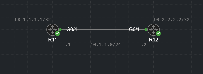
Concerning scenario 1, when you generate a ping on R11 using the ping 10.1.1.2 command, if you don’t specify the source of the ping, the router will use the interface “closest to the destination” as the source. How does it determine that? It looks at the routing table. The interface “closest to the destination” is actually the exit interface that would be used to reach the destination according to the routing table.

If you specify the source of the ping, using an interface or an IP address, then it doesn’t need to look at the routing table. Because a router has many interfaces (unlike a PC for example) it must somehow determine out of which interface to send the packet, even if the packet is generated by the router itself. If the actual command doesn’t specify the source interface of the communication, then the routing table must be used to choose that source interface.

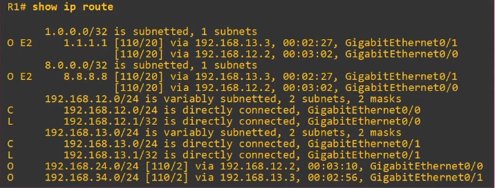
Concerning Scenario 2, in such a case, a routing table lookup would definitely take place. The destination IP is on a different subnet than the interface, thus, the routing table would be consulted to see where the packet should be sent. It would see that the destination is an interface on the router itself, but it would still use the routing table lookup to determine that.

Concerning Scenario 3, I am not familiar with the intricacies of the Windows OS, but I would agree with you that the Windows routing table is consulted. You described the process very well, and I belive that the description using the routing table simply gives more information about the mechanisms that are working in the background that make it all happen. I believe you have a good grasp of this process.

I hope this has been helpful!

Laz

Hello Laz,

Its been awhile since I asked this question, but I wanted to re-open discussion around this topic, particularly of how a router or multi layer switch would not have to look at its routing table to forward a packet if we were to include the source IP/interface of a ping in the scenario I described above.

Please find the topology below:

from the point of view of R11, if we were to ping R2’s interface 10.1.1.2 (or the loopback of R12) without specifying a source IP/interface, you mentioned a routing table look up would be necessary in order to determine the egress interface the router needs to use to reach that destination IP. That is perfectly clear. What I dont understand is how specifying the source IP/interface on the ping command would avoid a routing table lookup.

For example, from R11, if we ran the command ping 2.2.2.2 source g0/1 (or ping 2.2.2.2 source 10.1.1.1) the ping would fail unless we had an entry on our routing table that knows how to reach the 2.2.2.2/32 network. I understand we specified the egress interface here, but I dont see how that would be enough to forward that packet without having an entry in the RIB that matches the destination IP we want to reach, in which case we would still need to perform a routing table lookup even when specifying the source IP/interface.

So finally, my question would be how specifying the source IP/interface would negate having to look at our routing table when a router generates a packet? since doing this without an entry on our RIB that can match the destination IP of our packet always fails

Thank You Laz

Hello Paul

Thanks for your detailed question. In my post I was specifically talking about the scenario where you ping the 10.1.1.2 destination while specifying either the source IP address of 10.1.1.1 or the exit interface of Gi0/1. Looking at the routing table is used to determine the exit interface. If you specify the exit interface in your ping and the destination is on the same subnet as the source interface, then theoretically speaking, you don’t need any additional information from the routing table. It is for this reason that I said that a routing lookup is unnecessary.

My point was that such an action has enough information to perform the ping without looking up any information in the routing table. Now what actually happens depends upon the way that a particular routing device is designed to operate. Whether or not the routing table is actually referenced may depend upon the internal programming of the device itself.
It may actually use the routing table just out of its fundamental operation. However, theoretically speaking, it doesn’t really have to.

Now in the example you state where the destination is 2.2.2.2 which is outside of the subnet of the Gi0/1 interface, of course, the routing table must be referenced, and the destination address must be in the routing table, otherwise the ping will indeed fail.

I hope this has been helpful!

Laz

Hi,

I’m just trying to understand how CEF per-destination load sharing works when both next-hops are on the same network and via the same exit ethernet interface.

E.g.

R5#sh ip cef 9.9.9.0
9.9.9.0/24
nexthop 155.1.0.1 GigabitEthernet0/1
nexthop 155.1.0.3 GigabitEthernet0/1

I would expect per-destination to result in traffic to 9.9.9.9 to only use one of those next hops, however, trace routes show that both next hops are used.

R5#traceroute 9.9.9.9 source 5.5.5.5
Type escape sequence to abort.
Tracing the route to 9.9.9.9
VRF info: (vrf in name/id, vrf out name/id)
1 155.1.0.3 7 msec
155.1.0.1 5 msec
155.1.0.3 6 msec
2 155.1.146.6 8 msec
155.1.37.7 7 msec
155.1.146.6 8 msec
3 155.1.79.9 14 msec
155.1.67.7 15 msec *

Does that mean CEF is purely used for load balancing across physical links?

Hello Samir

First of all, let me clarify that CEF load-balancing balances traffic across available routes and not (necessarily) between interfaces. If multiple routes use the same exit interface or different exit interfaces is irrelevant as far as CEF load balancing goes.

Now when CEF determines the next hop for a packet, it uses a hash of the source and destination IP addresses (by default). This ensures that packets for the same flow (same source and destination IP) consistently use the same path. Based on this, you should indeed see the same next hop IP for all of your traceroute probes. Indeed, Cisco’s documentation states that:

You can use per-destination load balancing to ensure that packets for a given host pair arrive in order. All packets intended for a certain host pair are routed over the same link (or links).

Since seeing different paths in your traceroute output, CEF is not functioning like this. The only thing I can think of is that you may be using a platform that uses a slightly different hashing algorithm that may include other elements such as Layer 4 ports, which may be different for each individual probe. Alternatively, it could simply be an issue of a misconfiguration (i.e. you’ve enabled per-packet load balancing), but I’m quite sure you checked that :slight_smile:

The other thing I am thinking is that traceroute, as a utility, is used to test connectivity. Could it be that traceroute on the router itself overrides the CEF operation in order to test multiple next hop IP addresses in the multiple probes it sends? I know I’m reaching for straws here, but it’s just a thought. I haven’t read any documentation that states this, but I’m just thinking out loud.

I regret not being able to provide more information for this to resolve the reason for this behavior. If you do gain any more insight into this, please share it with us so that we can continue the conversation.

I hope this has been helpful!

Laz

Hello Samir

After an update from Rene, there is a more clear explanation for the differences you see! CEF can be configured to use the original or unversal algorithm. When the universal algorithm is used, multiple parameters are used as input. For more info, take a look at this NetworkLessons note and its links.

I hope this has been helpful!

Laz

Hi Laz,

Thanks very much for following up, those links explain it perfectly.

Per-destination is a misleading name as each flow is determined by many things, inc. ports, which change when using a traceroute.

Sam

1 Like

So, only data plane traffic is forwarded using FIB (CEF) right? And control plane traffic is forwarded using RIB?

Then why when you run “show ip cef“ there is an entry for,

224.0.0.0/24

Multicast Hello traffic is control plane traffic.

Correct me if my understanding is wrong.

Hello Pamod.

No, that’s not correct.

The data plane involves functions that are related to packet forwarding through the network.

Whenever a router looks for a matching route to forward a packet, that’s part of the data plane. It doesn’t matter if you use the RIB or FIB for this - packet forwarding and route lookups are part of the data plane.

FIB is something that CEF uses. Basically, the goal with FIB was to create a more optimized/easier version of the RIB. If you compare the two

The FIB is stripped off any extra information such as how the route was learned, what the AD and metrics are, and so on. It’s optimized and constructed for easier lookups and packet forwarding so if you use the FIB instead, you’ll be able to perform lookups faster.

The point is, regardless of whether you perform a route lookup by using the RIB or the FIB - all of that is part of the data plane.

Control plane involves functions that are often used to build something. For example, OSPF packets are part of the control plane as they are used to control and build the OSPF LSDB which then builds the routing table. STP is used to build a loop-free topology, ARP is used to build a table that contains the MAC/IP of the destination devices.

The control plane basically controls how the data plane will behave - which ports will be used, which routes will be used, and so on. The control plane does more of the “thinking” if I can put it that way.

If you run OSPF, OSPF will install the best routes into the routing table - that’s all the control plane. Then, the actual process of performing a route lookup and forwarding the packet based off the picked route is part of the data plane.

So building the FIB (or the RIB if you disable CEF) by using OSPF or other protocols is part of the control plane. After that is built, the actual packet forwarding and route lookups are part of the data plane.

Then why when you run “show ip cef“ there is an entry for,

224.0.0.0/24

Multicast traffic isn’t always control plane traffic. OSPF, EIGRP and so on are control plane protocols but remember that multicast has more use to it than just with routing protocols.

Imagine that you’re streaming a video. You have certain computers that are interested in receiving this video stream but not all of them. In this case, you could configure multicast and have the video server stream the video to a particular multicast address such as 239.1.1.1. The interested receivers would then “subscribe” to this multicast address and receive packets for it.

As the multicast stream is being transmitted, it will eventually be routed to reach hosts like H4. In this case, the routers need to have a relevant multicast routing table entry to perform route lookups and packet forwarding - which is again, all part of the data plane.

Multicast is a big topic so I am only providing a very high-level overview here. The point here is to understand that multicast traffic doesn’t always have to be control plane traffic, the use is pretty much up to you - based off what your requirements are and what protocols you’re running.

If you have any further questions, feel free to ask!

David

1 Like

Hey, thank you for the detailed explanation. Very much appreciated.

1 Like

Hello @pamod.inbox and @davidilles

Just wanted to clarify the conversation a bit. There is some truth to your statement here:

Control plane traffic is traffic that is primarily sourced and destined to network devices such as routers due to its nature. This includes routing protocols at Layer 3 and protocols at Layer 2 such as STP, CDP, and VDP. As far as Layer 3 protocols go, some of them need routing to function such as the exchange of routing updates.

Because these routing updates are typically sourced and destined to routers themselves, when such packets are received, they are not routed using CEF. They are processed using punts (to send to more conventional routing processes), so CEF doesn’t process them.

So control plane traffic is not processed by CEF, but it is punted to fast/process switching simply because it is destined for the local device by its very nature.

Now, specifically, concerning the 224.0.0.0/24 entry in CEF, it serves a particular purpose. If you take a look at the entry itself, you see this. Notice the Next Hop entry:

Router#show ip cef 224.0.0.0
Prefix              Next Hop             Interface
224.0.0.0/24        receive

The “receive” action tells the data plane to punt this traffic to the control plane for processing, rather than forward it normally. So, the FIB doesn’t just contain forwarding entries, it also contains exception entries that tell the data plane how to handle special cases. The 224.0.0.0/24 entry is essentially saying: “When you see this traffic, don’t try to forward it, send it up to the non-CEF routing process instead.” This is a special case because this particular multicast group is specifically designed for use with control plane traffic. Does that make sense?

I hope this has been helpful!

Laz

If the switch loses it power, does the TCAM loses its memory?

Hello David

The short answer is yes. Let me explain in detail…

TCAM is a type of volatile memory, similar to DRAM, and needs constant power to retain its contents. If power is lost, it will lose its contents. When the switch comes back online, it will automatically rebuild the TCAM tables from non-volatile sources (like the startup configuration and routing tables), and will continue to repopulate it as traffic traverses the device.

In general, this is not a huge loss, because the TCAM contents, whether used for CEF or anything else, is rebuilt during normal operation, and generally speaking, it is rebuilt quite fast, and it quickly regains operational efficiency.

I hope this has been helpful!

Laz

Thank you. I understand now.