Rene,
Thanks for the help - that actually makes more sense now (the design complexity of this router is… interesting).
I’ve added the local LAN address, and the router table entries are now as you described, and I can ping through the router (both ways) to the 172.16.0.1 interface (local LAN gateway).
Here’s the ip route and ping info
Gateway of last resort is 0.0.0.0 to network 0.0.0.0
  S*    0.0.0.0/0 is directly connected, GigabitEthernet0/1
        10.0.0.0/8 is variably subnetted, 4 subnets, 2 masks
  C        10.1.1.0/24 is directly connected, Vlan1
  L        10.1.1.254/32 is directly connected, Vlan1
  C        10.1.10.0/24 is directly connected, Vlan10
  L        10.1.10.254/32 is directly connected, Vlan10
            11.0.0.0/8 is variably subnetted, 2 subnets, 2 masks
  C        11.11.11.0/24 is directly connected, wlan-ap0
  L        11.11.11.11/32 is directly connected, wlan-ap0
           172.16.0.0/16 is variably subnetted, 2 subnets, 2 masks
 C        172.16.0.0/24 is directly connected, GigabitEthernet0/1
  L        172.16.0.251/32 is directly connected, GigabitEthernet0/1
  Router#ping 172.16.0.1
  Type escape sequence to abort.
  Sending 5, 100-byte ICMP Echos to 172.16.0.1, timeout is 2 seconds: !!!!!
  Success rate is 100 percent (5/5), round-trip min/avg/max = 1/1/1 ms
  Router#ping 8.8.8.8
  Type escape sequence to abort.
  Sending 5, 100-byte ICMP Echos to 8.8.8.8, timeout is 2 seconds: .....
  Success rate is 0 percent (0/5)
  Router#
As you can see, while I can ping the gateway, I don’t have internet access or DNS resolution. I’m guessing it’s a NAT issue, but I’m not sure where to go next.
I see you have a default route, pointing to your GigabitEthernet0/1 interface. This will work but for performance reasons, it’s best to replace it with a default route that points to the next hop address of your gateway:
0.0.0.0 0.0.0.0 172.16.0.1.
If you want to know why, there’s a good example on the Cisco community forum here:
With your default route, your 1941 is able to forward packets to 172.16.0.1. If you send a ping from your 1941 to 8.8.8.8, it should send a packet from 172.16.0.251 (Gigabit Ethernet 1 interface). Just to be sure, you can try a ping and set the source interface:
ping 8.8.8.8 source GigabitEthernet 1
This ping should work as it’s similar to sending a ping from any computer on your LAN. The second thing you should try is sending a ping with a different source. For example, the VLAN 10 interface:
ping 8.8.8.8 source Vlan 10
This ping should fail since your gateway won’t know how to reach 10.1.10.0/24. You will have to add a static route on your gateway that points to the 1941. Something like this:
10.1.10.0 255.255.255.0 172.16.0.251
This helps your gateway to find the 10.1.10.0/24 network and send the return packets. I’m not sure what gateway you are using but you might have to make some changes to NAT too. You will have to make sure that NAT also translates packets from the 10.1.10.0/24 subnet.
Rene,
Thanks for the response - sorry for the delay, work has had me out of pocket for a bit.
I applied the routing changes you indicated, and things still didn’t work, which didn’t make a lot of sense, so I moved the 1941W from our sister company’s LAN to our network and it works just fine.
It seems the router / gateway they have (an early model Netgear) doesn’t handle NAT or static routing properly, I spent some time trying firmware and config changes and still no joy, so I’ve recommended they replace their router.
We considered using the 1941W, but I’m no where near experienced enough to lock down the security.
One last question, while I’m able to enter the ap#config at the CLI, when I try to select WiFi on the GUI, it keeps asking for a username and password, and no matter what I try it doesn’t authenticate.
Can you tell me where to set the creds for the GUI WiFi configuration access?
It’s always a challenge with some lower end routers to make things work. Some SOHO routers will only do NAT for the subnet on their LAN interface and others don’t even support static routing. If you have the 1941W, it’s not a bad idea to use it for Internet access. Not sure which license you have but the zone based firewall is nice to have:
I can’t test it but I think you can set the username/password for the GUI like this. Do this on the AP console:
ip http authentication local
username ADMIN password PASSWORD
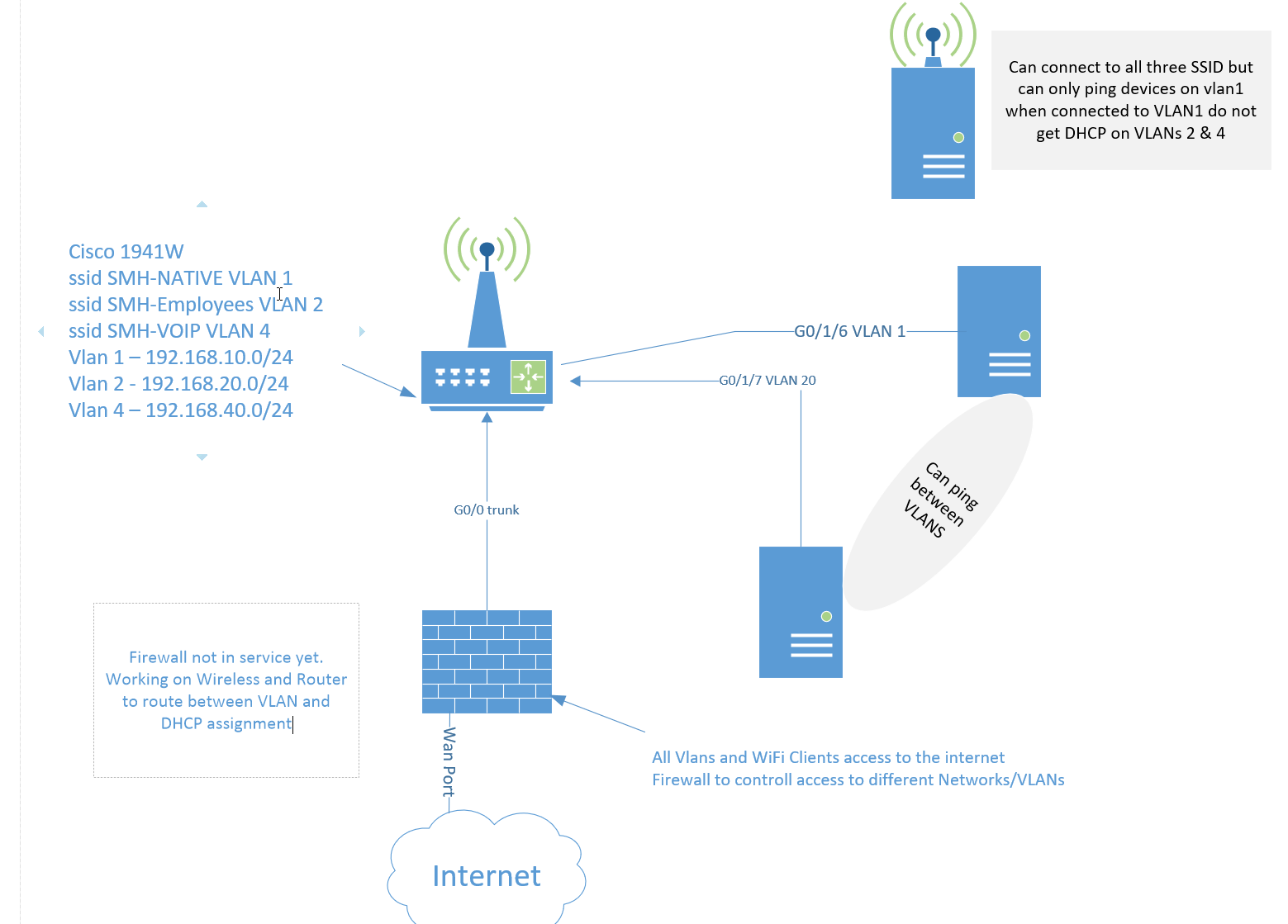
On the wired side I can ping devices on different VLANs across the wire.
On the WiFi I can only ping devices on vlan1 and get a DHCP assignment. Vlan 2 & 3 can not ping and no DHCP.
Thanks for looking
AP Config
Current configuration : 3206 bytes
!
version 12.4
no service pad
service timestamps debug datetime msec
service timestamps log datetime msec
service password-encryption
!
hostname ap
!
logging rate-limit console 9
enable secret 5 $1$YkUa$k/lBfSWQHoM2uh/VsFgdb.
!
no aaa new-model
!
!
dot11 syslog
!
dot11 ssid SMH-Employees
vlan 2
authentication open
authentication key-management wpa version 2
mbssid guest-mode
wpa-psk ascii 7 096D63272924242159
!
dot11 ssid SMH-NATIVE
vlan 1
authentication open
authentication key-management wpa version 2
mbssid guest-mode
wpa-psk ascii 7 1128342B2733383F55
!
dot11 ssid SMH-VOIP
vlan 4
authentication open
authentication key-management wpa version 2
mbssid guest-mode
wpa-psk ascii 7 14363F253C25191877
!
!
!
username Cisco password 7 047802150C2E
!
!
bridge irb
!
!
interface Dot11Radio0
no ip address
no ip route-cache
!
encryption vlan 1 mode ciphers aes-ccm
!
encryption vlan 2 mode ciphers aes-ccm
!
encryption vlan 4 mode ciphers aes-ccm
!
ssid SMH-Employees
!
ssid SMH-NATIVE
!
ssid SMH-VOIP
!
antenna gain 0
mbssid
station-role root
!
interface Dot11Radio0.1
encapsulation dot1Q 1 native
no ip route-cache
bridge-group 1
bridge-group 1 subscriber-loop-control
bridge-group 1 block-unknown-source
no bridge-group 1 source-learning
no bridge-group 1 unicast-flooding
bridge-group 1 spanning-disabled
!
interface Dot11Radio0.2
encapsulation dot1Q 2
no ip route-cache
bridge-group 2
bridge-group 2 subscriber-loop-control
bridge-group 2 block-unknown-source
no bridge-group 2 source-learning
no bridge-group 2 unicast-flooding
bridge-group 2 spanning-disabled
!
interface Dot11Radio0.4
encapsulation dot1Q 4
no ip route-cache
bridge-group 4
bridge-group 4 subscriber-loop-control
bridge-group 4 block-unknown-source
no bridge-group 4 source-learning
no bridge-group 4 unicast-flooding
bridge-group 4 spanning-disabled
!
interface Dot11Radio1
no ip address
no ip route-cache
shutdown
antenna gain 0
dfs band 3 block
channel dfs
station-role root
bridge-group 1
bridge-group 1 subscriber-loop-control
bridge-group 1 block-unknown-source
no bridge-group 1 source-learning
no bridge-group 1 unicast-flooding
bridge-group 1 spanning-disabled
!
interface GigabitEthernet0
description the embedded AP GigabitEthernet 0 is an internal interface connecting AP with the host router
no ip address
no ip route-cache
!
interface GigabitEthernet0.1
encapsulation dot1Q 1 native
no ip route-cache
bridge-group 1
no bridge-group 1 source-learning
bridge-group 1 spanning-disabled
!
interface GigabitEthernet0.2
encapsulation dot1Q 2
no ip route-cache
!
interface GigabitEthernet0.4
encapsulation dot1Q 4
no ip route-cache
!
interface BVI1
ip address 192.168.10.2 255.255.255.0
no ip route-cache
!
interface BVI2
ip address 192.168.20.2 255.255.255.0
no ip route-cache
!
interface BVI4
ip address 192.168.40.2 255.255.255.0
no ip route-cache
!
ip default-gateway 192.168.20.1
ip http server
no ip http secure-server
ip http help-path http://www.cisco.com/warp/public/779/smbiz/prodconfig/help/eag
bridge 1 route ip
!
!
!
line con 0
no activation-character
line vty 0 4
login local
!
Router Config
Building configuration...

Current configuration : 3235 bytes
!
! Last configuration change at 20:19:17 UTC Mon Dec 14 2020
version 15.1
service timestamps debug datetime msec
service timestamps log datetime msec
no service password-encryption
!
hostname Router
!
boot-start-marker
boot-end-marker
!
!
!
no aaa new-model
!
service-module wlan-ap 0 bootimage autonomous
!
no ipv6 cef
ip source-route
ip cef
!
!
!
ip dhcp excluded-address 192.168.10.1 192.168.10.30
ip dhcp excluded-address 192.168.20.1 192.168.20.30
ip dhcp excluded-address 192.168.40.1 192.168.40.30
!
ip dhcp pool SMH-NATIVE
network 192.168.10.0 255.255.255.0
dns-server 8.8.8.8
default-router 192.168.10.1
!
ip dhcp pool SMH-Employees
network 192.168.20.0 255.255.255.0
default-router 192.168.20.1
dns-server 8.8.8.8
!
ip dhcp pool SMH-VOIP
network 192.168.40.0 255.255.255.0
default-router 192.168.40.1
dns-server 8.8.8.8
!
!
!
multilink bundle-name authenticated
!
crypto pki token default removal timeout 0
!
!
license udi pid CISCO1941W-A/K9 sn FTX161683ET
license boot module c1900 technology-package securityk9
hw-module ism 0
!
!
!
vtp domain Houston
vtp mode transparent
!
redundancy
!
!
!
!
vlan 2-4
!
vlan 7
name 104F-Primary
!
vlan 8
name 104F-IOT
!
vlan 9
name 104F-GUEST
!
vlan 10
name WIFI
!
vlan 11,13
!
vlan 20
name home
!
vlan 30
name comcast
!
vlan 70
name WIFI70
!
vlan 80
name WIFI80
!
vlan 100
!
!
!
!
!
!
!
!
interface Embedded-Service-Engine0/0
no ip address
!
interface GigabitEthernet0/0
no ip address
shutdown
duplex auto
speed auto
!
interface wlan-ap0
description Service module interface to manage the embedded AP
ip unnumbered Vlan1
arp timeout 0
no mop enabled
no mop sysid
!
interface GigabitEthernet0/1
no ip address
shutdown
duplex auto
speed auto
!
interface Wlan-GigabitEthernet0/0
description uplink to AP
switchport mode trunk
no ip address
!
interface GigabitEthernet0/0/0
no ip address
!
interface GigabitEthernet0/0/1
no ip address
!
interface GigabitEthernet0/0/2
no ip address
!
interface GigabitEthernet0/0/3
no ip address
!
interface GigabitEthernet0/1/0
no ip address
!
interface GigabitEthernet0/1/1
no ip address
!
interface GigabitEthernet0/1/2
no ip address
!
interface GigabitEthernet0/1/3
no ip address
!
interface GigabitEthernet0/1/4
no ip address
!
interface GigabitEthernet0/1/5
no ip address
!
interface GigabitEthernet0/1/6
no ip address
!
interface GigabitEthernet0/1/7
switchport access vlan 2
no ip address
!
interface Vlan1
description SMH-NATIVE
ip address 192.168.10.1 255.255.255.0
!
interface Vlan2
description SMH-Employees
ip address 192.168.20.1 255.255.255.0
!
interface Vlan4
description SMH-VOIP
ip address 192.168.40.1 255.255.255.0
!
!
router eigrp 10
network 0.0.0.0
If users connected wirelessly to VLANs 2 and 4 can’t obtain IP addresses via DHCP, then this is why there is no connectivity with other VLANs. So the source of the problem is that wireless clients on the SSIDs that correspond to VLANs 2 and 4 can’t get IP addresses using DHCP.
Now in order to get these addresses, these clients should have connectivity to the DHCP server which looks to be set up correctly on the 1941W. Take a look however at the subinterfaces configured on the AP. I notice that for GigabitEthernet0.1 you have configured the bridge group, but not on GigabitEthernet0.2 and 0.4. This means that wirelessly connected devices to the Dot11Radio0.2 and Dot11Radio0.4 interfaces cannot be bridged with those GigabitEthernet sub-interfaces, and thus cannot communicate with the DHCP server on the router. See if adding this configuration will resolve your problem.
I do not like when it’s that simple. I found another configuration sample and it is working, it does have the bridge-groups in there. In fact I now have more vlans than the original config while redesigning my home/lab network. But on the wireless side my devices only want to connect to dot11radio 0 (2.4ghz) and not the dot11radio 1 (5ghz). If I shut down dot11radio 0 they connect to the dot11radio 1 side. Any suggestions other than separate vlans for Dot1 Radios? Band preference/selection? Would like not to have different SSID per dot11radio? Thank you for the response.
When you have two radios with the same SSID, one functioning at 2.4GHz and the other at 5GHz, and if you have a client that supports both, then there is no way to force a client to prefer one over the other. Each client, depending upon the chipset/vendor, has internal processes that choose to which one it will connect. Criteria such as RSSI, beacon response times as well as other factors can affect the choice from the client point of view.
Now there is a feature called Band Steering that can help to coax a client to prefer the 5GHz band instead. From a quick search, I can’t find any info on this feature for the 1941W router, so I assume it doesn’t support it. However, if you simply want to find out more about what it is and how it works, there’s an excellent explanation at this Cisco Meraki documentation:
Even with this feature, you can’t guarantee that the client will still choose one band over the other, as the ultimate decision is up to the client itself.
The only way to do it in your case is to use a different SSID and have the client choose the correct one.
Can you tell us a little bit more about your configuration? Can you share some of the configurations and the results you see so that we can help you troubleshoot further?
Hello,
I’ve used your page Cisco 1941W Wireless Configuration Example to setup my Cisco 1941W but can’t seem to get the SSID’s to broadcast. See below for my configuration. I haven’t configured any routing on the router yet but will be using OSPF and NAT. I’m fairly new to Cisco CLI and to the 1941W. Any help would be great.
Thank you
AP configuration:
Building configuration...

Current configuration : 2016 bytes
!
version 12.4
no service pad
service timestamps debug datetime msec
service timestamps log datetime msec
no service password-encryption
!
hostname ap
!
enable secret 5 $1$haqC$HUWced9/W7QhhazP7oQ5a/
!
no aaa new-model
!
!
dot11 syslog
!
dot11 ssid cisco
!
dot11 ssid cisco 2.4
   authentication open
   authentication key-management wpa
   guest-mode
   wpa-psk ascii 0 test1234
!
!
!
username admin privilege 15 secret 5 $1$hsz2$90mtbt1Q2J7jJ2Nwpg5bT/
!
!
bridge irb
!
!
interface Dot11Radio0
 description 2.4GHz Radio
 no ip address
 no ip route-cache
 !
 encryption mode ciphers aes-ccm
 !
 ssid cisco
 !
 antenna gain 0
 station-role root
 bridge-group 1
 bridge-group 1 subscriber-loop-control
 bridge-group 1 block-unknown-source
 no bridge-group 1 source-learning
 no bridge-group 1 unicast-flooding
 bridge-group 1 spanning-disabled
!
interface Dot11Radio1
 description 5GHz Radio
 no ip address
 no ip route-cache
 !
 encryption mode ciphers aes-ccm
 !
 ssid cisco
 !
 antenna gain 0
 dfs band 3 block
 channel dfs
 station-role root
 no cdp enable
 bridge-group 10
 bridge-group 10 subscriber-loop-control
 bridge-group 10 block-unknown-source
 no bridge-group 10 source-learning
 no bridge-group 10 unicast-flooding
 bridge-group 10 spanning-disabled
!
interface GigabitEthernet0
 description the embedded AP GigabitEthernet 0 is an internal interface connecting AP with the host router
 no ip address
 no ip route-cache
 bridge-group 1
 no bridge-group 1 source-learning
 bridge-group 1 spanning-disabled
!
interface GigabitEthernet0.10
 encapsulation dot1Q 10
 no ip route-cache
 bridge-group 10
 no bridge-group 10 source-learning
 bridge-group 10 spanning-disabled
!
interface BVI1
 ip address 192.168.3.2 255.255.255.0
 no ip route-cache
!
ip http server
no ip http secure-server
ip http help-path http://www.cisco.com/warp/public/779/smbiz/prodconfig/help/eag
bridge 1 route ip
!
!
!
line con 0
 privilege level 15
 login local
 no activation-character
line vty 0 4
 login local
!
cns dhcp
end

--------------------------------------------------------------------------------
Router config

HOMERTRAP#show run
Building configuration...


Current configuration : 1911 bytes
!
version 15.7
service timestamps debug datetime msec
service timestamps log datetime msec
no service password-encryption
!
hostname HOMERTRAP
!
boot-start-marker
boot-end-marker
!
!
enable secret 5 $1$98/M$uVvmdn2y9vRt4L9rUcxQb0
enable password
!
aaa new-model
!
!
aaa authentication login default local enable
!
!
!
!
!
!
aaa session-id common
service-module wlan-ap 0 bootimage autonomous
!
!
!
!
!
!
!
!
!
!
!
!
!
!
!
!


!
!
ip dhcp pool VLAN-WIFI
 network 192.168.4.0 255.255.255.0
 default-router 192.168.4.1
 dns-server 8.8.8.8
!
!
!
ip domain name homertrap.local
ip cef
no ipv6 cef
!
multilink bundle-name authenticated
!
!
!
!
license udi pid CISCO1941W-A/K9 sn xxxxxxxxx
hw-module ism 0
!
!
!
username admin password 0
!
redundancy
!
!
!
!
!
!
!
!
!
!
!
!
!
!
!
interface Embedded-Service-Engine0/0
 no ip address
 shutdown
!
interface GigabitEthernet0/0
 ip address 192.168.0.5 255.255.255.0
 duplex auto
 speed auto
!
interface wlan-ap0
 ip address 11.11.11.11 255.255.255.255
 arp timeout 0
 no mop enabled
 no mop sysid
!
interface GigabitEthernet0/1
 no ip address
 shutdown
 duplex auto
 speed auto
!
interface Wlan-GigabitEthernet0/0
 switchport mode trunk
 no ip address
!
interface Serial0/1/0
 no ip address
 shutdown
!
interface Vlan1
 ip address 192.168.3.1 255.255.255.0
!
interface Vlan10
 ip address 192.168.4.1 255.255.255.0
!
ip forward-protocol nd
!
no ip http server
no ip http secure-server
!
!
ipv6 ioam timestamp
!
!
!
!
!
control-plane
!
!
line con 0
line aux 0
line 2
 no activation-character
 no exec
 transport preferred none
 transport output lat pad telnet rlogin lapb-ta mop udptn v120 ssh
 stopbits 1
line 67
 no activation-character
 no exec
 transport preferred none
 transport input all
 transport output lat pad telnet rlogin lapb-ta mop udptn v120 ssh
line vty 0 4
 password
 transport input ssh
!
scheduler allocate 20000 1000
!
end
Looking over your config, at first glance, there doesn’t seem to be anything obvious causing the SSID from being broadcast. Do some verification of the interfaces by taking a look at the state of the interfaces using the show ip interface brief command. Also, you may find this Cisco documentation useful as well.
Let us know how you get along in your troubleshooting, and if you have something more specific, let us know!
If I understand correctly, you want to configure your 1941W router so that both the wired and wireless networks are on the same network segment, correct? In that way, both your wireless clients and your wired hosts will have an IP address in the range of 10.0.0.0/24.
Yes, this is possible, and you can do this by creating a bridged network configuration. Specifically:
To configure a bridged network on the Cisco 1941W router, you will need to perform the following steps:
Configure the LAN interfaces:
Connect your wired devices to the LAN interface on the router.
Assign an IP address and subnet mask to the LAN interface using the “interface” command in global configuration mode.
Configure the wireless interface:
Enable the wireless interface using the “interface wlan0” command in global configuration mode.
Configure the SSID and security settings for the wireless network using the “ssid” and “encryption” commands in the wlan interface configuration mode.
Assign the same IP address and subnet mask to the wireless interface as the LAN interface using the “ip address” command in the wlan interface configuration mode.
Bridge the interfaces:
Create a bridge group using the “bridge” command in global configuration mode.
Add the LAN and wireless interfaces to the bridge group using the “bridge-group” command in their respective interface configuration modes.
Once you have completed these steps, the wired and wireless interfaces will be bridged and devices connected to either interface will be on the same layer 2 network segment and share the same IP subnet.
I am very new to CISCO Devices. Got a CISCO 1941W and trying to setup a WiFi at home. Kindly advise how we came to this config-t mode form AP#
Ap#
Our next move is to configure the gigabit interface of the access point. We will use the BVI interfaces to tell the interface to which VLANs it belongs: Ap(config-if)#interface gigabitEthernet 0
If you can give me the commands in between Ap# and Ap(config-ig)# - where I can enter interface gigabitEthernet 0 that will be great.
You’re right, there is a command missing that tells you how to get from one input mode to another. But it seems that there is a typo in the prompts that you see in the lesson as well, slightly complicating things . In the following correction, I am fixing the errors and adding the appropriate intermediate commands to give you the full picture:
Ap>enable
Password: Cisco
Ap#
Our next move is to configure the gigabit interface of the access point. We will use the BVI interfaces to tell the interface to which VLANs it belongs: