Cisco Network Time Protocol (NTP)

Hello Sreejith,

NTP and PTP are applications (layer 7 of the OSI model).

These two protocols are mainly used so that other applications have the correct time/date. Think of stuff like logging information or network management. You want to have the correct timestamps on your log lines, and you want it to be the same on all your devices.

Clocking for interfaces is usually done on layer 1. If you would do it on a higher layer, you get into a chicken and egg issue…

How can you use a clocking mechanism on let’s say layer 7 if layer 1/2/3/4/5/6 are not operational yet? :slight_smile:

Hope this helps!

Rene

1 Like

Hi Rene,
Thanks for your reply . Now I understood about NTP and PTP. I just wonder about how about traffic(packet) flow inside of an ISP as I didn’t get chance to work\vision inside of it :wink: I know when we connect router’s serial interfaces we have to set one end as DTE and other as DCE(belongs to ISP) for layer 1 signal synchronization (for matching speed). Does internet service use any kind of external clocking devices along with routers or using routers hardware clocks ? I only know Ethernet is asynchronous we don’t need any external clock signal to carry data signal but Serial interfaces needs clocking signal to carry data , Could you please brief a little more about the needs of clocking signal (layer-1) in ISP environment(WAN).:slight_smile:
Thanks,
Sreejith

Hello Sreenath

Concerning the clocking mechanism for serial connections. This is a mechanism that is different from the clock on the device. The clock on the device is the actual current date and time.

The clocking signal or the clock rate on a serial connection is really just a method of stating how fast the bits will be sent on the circuit. It can also be viewed as the configured bandwidth on the serial connection. A clock rate of 9600 will send 9600 bits every second for example.

As you said, this clocking signal is usually sent by the ISP or the serial circuit provider as they are responsible for setting the bandwidth of the circuit based on the contract that you as a subscriber have set up with them.

I hope this has been helpful!

Laz

Hi Rene,

I would like some clarity on your statement when Corerouter goes down, SW1 and SW2 can update or synch each other’s clock by using the ntp peer feature. If the Corerouter is the NTP master and it gets it’s time from an external clock, does this mean NTP is still working for SW1 and SW2 eventhough there are no alternate NTP servers?

Hello blue

Keep in mind that NTP as a protocol is responsible for periodic verification and resyncing of device clocks. This means that if a device is synced today, it will most likely keep reliable time for several days, weeks or even more.

So in the example that concerns your question, if the Core device’s NTP configuration fails, and SW1 and SW2 can no longer sync with that device, they will still keep reliable time for the next while simply because their clocks are still functioning. NTP will still operate on SW1 and SW2, and they will be querying the Core device for NTP information, but no response will come since it is down. However, the two switches have the option, if it is configured, to at least remain synchronised with each other using the NTP peer feature, which is important especially for troubleshooting and for making sense syslog info.

I hope this has been helpful!

Laz

1 Like

I seem to be having trouble with the NTP authentication. I have no problem configuring NTP using unicast, broadcast or multicast. However when I try to add authentication into my lab my NTP associations never go down. Also If i start the lab from scratch configuring authentication on the NTP server before adding any clients, then I add the clients without specifying a key the NTP association still comes up. Could someone take a look at my configs and tell me what I am doing wrong?

R1 NTP SERVER

ntp authentication-key 1 md5 1326343C3B 7
ntp authenticate
ntp trusted-key 1
ntp master

R2 NTP client

ntp server 10.1.1.1

Am I crazy or with the above config should R2 fail to make an NTP association? Thanks for any help you can provide!

Hello Kevin,

NTP authentication can be confusing. With your configuration, no authentication occurs because the client isn’t configured for authentication. I did a quick lab with your configuration.

The server will send “regular” NTP packets without an MD5 hash. Once you change the ntp server command on the client, it works.

Before:

https://www.cloudshark.org/captures/c40ea3a2748b

After:

Client(config)#ntp server 192.168.1.1 key 1

https://www.cloudshark.org/captures/e016b1c2e8a8

Once the client wants to use authentication, the server responds with the same MD5 hash. It doesn’t let you prevent clients from using your NTP server.

Hope this helps!

Rene

1 Like

Hi Rene

Does that mean that even once you configure an authentication key on the server, it will continue to accept plain-text clients anyway?

---

Also with the master command, where would you apply the ACL so it can talk to itself (127.127.7.1/127.127.1.1)

1 Like

I am wondering the same thing as Chris. If anyone has any explanation please let us know!

Thanks,
Scott

Hello Chris

Based on the following Cisco documentation, a device will drop any packets that fail the authentication check and prevent them from updating the local clock.

However, the configured authentication only restricts the NTP client from accepting the synchronisation or not. If another NTP client without authentication attempts to connect and synchronise, it will be able to. The authentication check is always done on the client side.

So if you were to configure this in the CoreRouter, you would have to add the following command:

CoreRouter(config)#ntp master
CoreRouter(config)#access-list 1 permit 127.127.7.1
CoreRouter(config)#ntp access-group peer 1

I hope this has been helpful!

Laz

1 Like

Hi Rene,

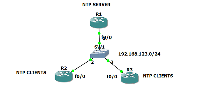
I have a small doubt regarding NTP packets exchange.Here is my topology

NTP

I have configured R1 has my NTP Server using NTP Master command.

R1 configuration:

ntp master
access-list 1 permit 127.127.7.1
ntp access group peer1

R2 configuration:

ntp server 192.168.123.1

R3 configuration:

ntp server 192.168.123.1

My Question:

when i tired to check clock synchronization status on R2 and R3 using ntp association and ntp status.

My clock was not getting synchronized on both R2 and R3.When i tried to perform debug ntp packets on R1.i can see ntp packets are sent from r1 to ntp server there was no reply from ntp server.I have checked whether any ACL is blocking the return packets from ntp server.but there is no acl configured.But when i configured R2 and R3 as ntp clients allowed to get updates from NTP server .my clock got synchronized

My Question:

Do we need to permit R2 and R3 through ACL on R1 (NTP Server) to get the clock synchronized ?

R2(config)#do sh ntp association

      address         ref clock     st  when  poll reach  delay  offset    disp
 ~192.168.123.1    0.0.0.0          16     -    64    0     0.0    0.00  16000.
 * master (synced), # master (unsynced), + selected, - candidate, ~ configured

R3#show ntp associations

      address         ref clock     st  when  poll reach  delay  offset    disp
 ~192.168.123.1    0.0.0.0          16     -    64    0     0.0    0.00  16000.
 * master (synced), # master (unsynced), + selected, - candidate, ~ configured

NTP Debug packets;

R2#
*Mar  1 00:44:47.755: NTP: xmit packet to 192.168.123.1:
*Mar  1 00:44:47.755:  leap 3, mode 3, version 3, stratum 0, ppoll 64
*Mar  1 00:44:47.755:  rtdel 0000 (0.000), rtdsp 10001 (1000.015), refid 00000000 (0.0.0.0)
*Mar  1 00:44:47.759:  ref 00000000.00000000 (00:00:00.000 UTC Mon Jan 1 1900)
*Mar  1 00:44:47.759:  org 00000000.00000000 (00:00:00.000 UTC Mon Jan 1 1900)
*Mar  1 00:44:47.759:  rec 00000000.00000000 (00:00:00.000 UTC Mon Jan 1 1900)
*Mar  1 00:44:47.759:  xmt C0294D7F.C17FCA1C (00:44:47.755 UTC Fri Mar 1 2002)

After adding the below ACL on R1 my clock ot synchronized

core-router(config)#ntp access-group serve-only 12
core-router(config)#access-list 12 permit 192.168.123.2
core-router(config)#access-list 12 permit 192.168.123.3

Hello Ganesh

It is not necessary to have an ACL on the clients in order to get NTP to sync. If you have no ACLs set on any of the devices, the syncing will function just like it shows in the lesson. However, if you enable the ntp access-group peer X command, even if it is to enable the loopback address of 127.127.7.1, and to configure the stratum, then you must add the ntp access-group serve-only Y command in order to specify from which clients you will accept NTP requests.

I hope this has been helpful!

Laz

Hi Las,

Thanks for the provide information.my questions do we need to allow the R2 and R3 ip on NTP server R1 through ACL.my clock was not getting synchronised at all after adding R2 and R3 has clients to NTP server through ACL my clock synchronised.

Hello Ganesh

Yes, you must include the IP addresses of the clients on the ACL of the NTP server in order to get the clocks synchronized.

Laz

SW2(config)#do sh ntp associations

  address         ref clock       st   when   poll reach  delay  offset   disp
 ~192.168.123.3   .LOCL.           1     17     64     7  9.770 135300.  0.944
 * sys.peer, # selected, + candidate, - outlyer, x falseticker, ~ configured

Hey Rene, this is the output I get after configuring SW2 to use 192.168.123.3 as the ntp server.
The ntp server is another router which I configured using the command ‘ntp master 1’, but I can’t understand why SW2 still refuses to use it.

Another question I have is regarding the Multicast and Broadcast configuration.
The topology is identical to yours, I configured everything you did and I have connectivity between SW2 SVI ‘Vlan 10’ and the router’s interface connected to it, but NTP doesn’t work.
Tried debugging but it doesn’t show anything.

SW2#vlan 10
      #exit
SW2#int vlan 10
      #ip add 192.168.1.1 255.255.255.0
      #ntp multicast 239.1.1.1
      #no sh
SW2#int gig0/0
      #sw mode access
      #sw acc vlan 10

And this is the router connected to it:

R2#int fa0/0
     #ip add 192.168.1.2 255.255.255.0
     #ntp multicast client 239.1.1.1

Hello Inon

There are several reasons why this might not be working:

  1. you just have to wait a little longer. NTP takes several minutes to synchronise, so if you wait long enough, it may indeed synchronise
  2. If you are using the master 1 command, keep in mind that the actual master must synchronise with its own clock using the 127.127.7.1 or 127.127.1.1 IP address. Make sure that these addresses are not blocked by the NTP access group configured. Also, if the device doesn’t synchronise with its own clock, it may not be able to allow clients to synchronise either. CHeck the status of NTP on the master device to see if this is the case.

Looking at your configuration at first glance I don’t see anything wrong with it. Can you try troubleshooting connectivity between interfaces? Also, take a look at the debugs of the NTP packets to see if they are being exchanged. Share your findings with us and we can go on to the next step of troubleshooting the issue together.

I hope this has been helpful!

Laz

Hello Laz,
I have a few questions and I am going to use the below topology as the reference.

My core routers are getting the time from a NTP server located in the internet and have the below configuration:

ntp server 146.185.130.223 prefer
ntp master 8

All the other Devices located in the LAN has the below configuration:

ntp server 192.168.1.1 prefer
ntp server 192.168.1.2

As far as my understanding goes, SW1 and SW2 will have stratum 9 since the core routers are hard coded to stratum 8. But in this case all of my LAN devices have stratum 3. I am not sure why. Would you please explain it to me?

show ntp status
Clock is synchronized, stratum 3, reference is 192.168.1.1

show ntp associations

  address                     ref clock                            st                    when        poll reach  delay  offset   disp
*~192.168.1.1    146.185.130.223                    2    
+~192.168.1.2    146.185.130.223                    2    

Now for security I am planning to configure them as below:

On the Core Routers
=========================

access-list 1 permit 146.185.130.223
ntp access-group peer 1

access-list 2 permit 172.16.0.1
access-list 2 permit 172.16.0.2
ntp access-group serve-only 2

On the LAN devices
====================

access-list 50 permit 192.168.1.1
access-list 50 permit 192.168.1.2
ntp access-group peer 50

Here, My goal is to restrict the core routers to allow to get updates only from 146.185.130.223 and allow only specific clients to get update from the core routers. Similarly, all the client devices located in the LAN will be allowed to get update only from those two core routers. Now, at this point of time, if any attacker sends a client request to one of my clients(for example SW1). Would SW1 respond to it? If it does, then I need to put a deny ACL in the client devices like below.

access-list 80 deny any
ntp access-group serve-only 80

Please let me know if all the syntax is correct or if I need to modify anything.

Thank you so much.

Best Regards,
Azm

Hello Azm

When you configure the ntp master command with a stratum number, this number will only be used to define the stratum of the device IF it cannot reach any clock with a lower stratum number. IF however a clock has been reached with a lower stratum number, as is the case with your configuration, the REAL stratum numbers will be used, both for the master and the clients that connect to it. If you temporarily disconnect the cores from their NTP sources and allow the NTP to update on all devices, the stratum number of SW1 and SW2 will indeed change to stratum 9.

Looking over your configuration parameters, at first glance all looks good. The switches should not respond to NTP requests but it is good practice to add the ACL that you did for NTP requests. If you implement this, please let us know how your testing goes.

I hope this has been helpful!

Laz

Hello Laz,
Thanks for your reply. Please explain why switches should not respond to NTP request. I have seen 6500 switches responding to the NTP request. Another thing is I am not sure if ACL is going to work in 3850/3750 switches because they don’t have routing enabled. I don’t even know if enabling routing is a prerequisite for ACL to work. Please help me to understand this. Thanks again.

Hello Azm

This was stated as a prerequisite in your previous post.

If you want them to respond, that’s fine as well, it all depends on what your requirements are. In order to block all NTP requests you can apply the access list as you originally stated it in your post.

As for the ACL, Cisco devices function as follows:

If you apply an ACL to a Layer 3 interface (physical or SVI) and routing is not enabled on the switch, the ACL only filters packets that are intended for the CPU, such as SNMP, Telnet, or web traffic.

This is taken from the following Cisco documentation:

So the ACL should function correctly. Having said that however, these ACLs in your config are applied using the ntp access-group command and not to the interface itself.

I hope this has been helpful!

Laz