DMVPN Phase 1 Basic Configuration

Hello Rob,
based on your previous post you are misunderstanding concept of different phases.

  • Hub is configured with “tunnel mode gre multipoint” in every DMVPN Phase (1, 2, 3).
  • Spokes are configured differently based on Phase you want to go with.
    Phase 1 is configured with “tunnel destination ip” on spokes. In DMVPN Phase 1 traffic between spokes goes always through the hub. This is definition of Phase 1.
    Phase 2 is configured with “tunnel mode gre multipoint” on spokes. Phase 2 allows direct spoke to spoke communication, thus traffic does not need to go through the hub anymore.
    Phase 3 is also configured with “tunnel mode gre multipoint” on spokes. Besides that you add “ip nhrp redirect” to the hub configuration and “ip nhrp shortcut” to spoke configuration. Phase 3 allows direct spoke to spoke traffic.

Both, Phase 2 and Phase 3, allows direct spoke to spoke traffic but the difference is how these phases are approaching direct spoke to spoke communication.

  • Phase 2 is done by tweaking routing protocol.
  • Phase 3 is done by tweaking NHRP protocol.

With Phase 2 you have to modify routing protocol behavior to suit your needs, for example split horzion rule for distance vector protocols, EIGRP next-hop-self, OSPF network type, configure iBGP route-reflector and such stuff. Specifically observe what is next-hop for route in RIB on spokes.
With Phase 3 you allow hub to send nhrp redirects, kind of a similar to icmp redirects. When you enable “ip hnrp shortcut” on spokes look for “H” routes in RIB.

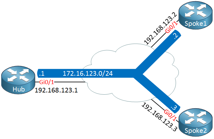
When you are mapping nhrp multicast to ip address on spokes you have to use “public” NBMA address there (NOT tunnel address of hub, but address on physical interface of hub), thus in your example:

should be:
ip nhrp map multicast 1.1.1.1

DMVPN is hard concept when you see it for first time and takes long time to master.
The best way how to get familiar with all this is to lab the hell out of it. Networklessons are providing really good material for DMVPN, you can find it in CCIE section. Trust me and go over all this material, lab it up. It takes time, but its worth it. Dont you want to become DMVPN ninja anyway?

3 Likes

HI,

I’m tryng to replicate this lab in a frame-relay topology without success.

I can reach the public IP of all devices but Tu0 interface of the spoke can’t reach the Hub and viceversa, can it work with frame-relay topology?

Thank you

Hello Giovanni,
can you please share your topology and configs, so I can look at it?

Hi Laz,

Could you explain briefly how communication happening b/w spokes, is here traffic will flow though hub or communication process will be same for all DMVPN phases?

Hello Pradyumna

If you take a look at this lesson, you will see a detailed description of how packets travel for DMVPN in each phase. Take a look at the sections of the lesson with the headers Phase 1, Phase 2, and Phase 3.

PS When you post your question, please post it in the relevant lesson topic rather than creating a new topic. This will help us to more quickly identify the question, and it eliminates the need of moving your question from topic to topic.

I hope this has been helpful!

Laz

Hi Laz,

1)I am unable to create topology like you b/c i am facing problem at cloud side, actually i want to know is cloud configure by us or we have to just connect it to our routers?

  1. secondly i want to know how is this possible to use single subnet on internet, as we know only directly connected routers can be connected in same subnet?, just to want to know all routers using same subnet ip how is is possible?

Kindly respond on it?

Hello Pradyumna

How you configure your DMVPN topology depends on your needs and your telco. In most cases, you are in control of all of your devices (hub and spokes) and you configure all of them. There may be situations where a telecom provider may provide you with the hub, and you simply configure the spokes appropriately, but again, it depends on the agreement that you’ve made with them. For the labs, you configure the hub and the spokes.

If you are able to secure the same subnet for all of your public IPs on your devices, then yes, you can use the same subnet. But this is highly unlikely unless your devices are in the same region (town or city), and you are using the same ISP for all of them. Typically, you would have public IP addresses as provided by each telco, and these are most likely not in the same subnet.

For the purpose of the labs, these IP addresses are in the same subnet simply for convenience. In real life, having them in the same or a different subnet will make no difference in the actual implementation, as long as there is IP connectivity between all devices.

I hope this has been helpful!

Laz

Thanks Laz and Kindly help me creating topology , as per the configuration in the topic you have not mentioned cloud configuration and it’s connectivity to the routers therefor i am not unable to do anything related to cloud( Configuration and connectivity both).

Hello Pradyumna

I’m not sure what you mean by “cloud configuration”. Do you mean the “cloud” found within the diagrams like this?
image
If you want to do a lab that matches the above topology, the only thing you need is to put a switch in the centre and connect the hub and spokes to that switch. Simply make sure that all interface IPs are in the same subnet and the routers can communicate with each other. This will create the underlay network, as described in the lesson, which, in a real-world example, would be the Internet itself, where all routers would have a public IP address so that they can ping each other. The DMVPN configuration on top of that is the overlay network, which will carry the user traffic and data.

If you need further clarification, please let me know.

I hope this has been helpful!

Laz

1 Like

Ok got it but if we can use switch then why are you using cloud?, if i am right you are using cloud just to represent sites are on wan network but actually it is a switch on internet ?

Hello Pradyumna

A cloud is being used in the diagrams because a real DMVPN topology will function over a network like the Internet. A DMVPN network would never be implemented on a local network with the use of a switch, except in a lab environment. However, I can see how this can cause confusion. I will let Rene know to see if he can clarify the lesson to avoid this confusion…

I hope this has been helpful!

Laz

1 Like

Hi Rene / Laz,

I recreated this lab, and whenever i shut and unshut the Tunnel of Hub, the DMVPN does not come up automatically, i have to either do same on each spoke or type “clear dmvpn session peer 172.16.123.1 static”

Can you let me know why this is happening.

Hello Justin

In order for a DMVPN connection to take place between a spoke and the HUB, the spoke sends an NHRP Registration request. The spoke initiates the communication. The HUB responds, and then the tunnel is established. If you shutdown the tunnel interface of the HUB, and then bring it back up again, the spokes are not aware of any such changes. When the tunnel interface comes back up, it does not send out any information to the spokes to say “hey I’m back up again” because all communication with the spokes has been lost, and remember that the initial connection is always initiated by the spokes.

So, you find that when you bring the HUB tunnel back up, you are not getting an established connection to the spokes right away. In order to have them reestablish right away, you need to shut and no shut the tunnel interfaces of the spokes.

I labbed this up and duplicated your results. However, if you wait long enough, the spokes will eventually send a keepalive to the HUB and will realize that the connection had failed, and will send a new NHRP registration to re-establish connectivity.

I hope this has been helpful!

Laz

Thanks for your reply.

So, just a curiosity, is there a way to make it quicker.

Hello Justin

Yes, it is possible to adjust this parameter, and it has to do with the NHRP registration process. NHRP is governed by a few timers, including the holdtime and the timeout. More detail on these timers and the way the function can be found at this Cisco documentation:

I hope this has been helpful!

Laz

Hi Rene,

I am trying to inject default route from Hub, but its not working… could you please look at the configuration and let me know what’s wrong…

Also please advise how can i send summary route towards spoke routers

Hub#show run int tu1
Building configuration...

Current configuration : 286 bytes
!
interface Tunnel1
 ip address 192.168.1.1 255.255.255.0
 no ip redirects
 ip nhrp authentication DMVPN
 ip nhrp map multicast dynamic
 ip nhrp network-id 1
 no ip split-horizon
 ip summary-address rip 0.0.0.0 0.0.0.0
 tunnel source GigabitEthernet1/0
 tunnel mode gre multipoint
end

Hub#

spoke1#show run int tu2
    Building configuration...

Current configuration : 266 bytes
!
interface Tunnel2
 ip address 192.168.1.2 255.255.255.0
 ip nhrp authentication DMVPN
 ip nhrp map 192.168.1.1 1.1.1.1
 ip nhrp map multicast 1.1.1.1
 ip nhrp network-id 1
 ip nhrp nhs 192.168.1.1
 tunnel source GigabitEthernet1/0
 tunnel destination 1.1.1.1
end

spoke1#


spoke2#show run int tu3
Building configuration...

Current configuration : 266 bytes
!
interface Tunnel3
 ip address 192.168.1.3 255.255.255.0
 ip nhrp authentication DMVPN
 ip nhrp map 192.168.1.1 1.1.1.1
 ip nhrp map multicast 1.1.1.1
 ip nhrp network-id 1
 ip nhrp nhs 192.168.1.1
 tunnel source GigabitEthernet2/0
 tunnel destination 1.1.1.1
end

spoke2#

Hub#show dmvpn
Legend: Attrb --> S - Static, D - Dynamic, I - Incomplete
        N - NATed, L - Local, X - No Socket
        # Ent --> Number of NHRP entries with same NBMA peer
        NHS Status: E --> Expecting Replies, R --> Responding, W --> Waiting
        UpDn Time --> Up or Down Time for a Tunnel
==========================================================================

Interface: Tunnel1, IPv4 NHRP Details
Type:Hub, NHRP Peers:2,

 # Ent  Peer NBMA Addr Peer Tunnel Add State  UpDn Tm Attrb
 ----- --------------- --------------- ----- -------- -----
     1 1.1.1.2             192.168.1.2    UP 00:01:23     D
     1 1.1.1.3             192.168.1.3    UP 00:01:22     D

Hub#

Hub#show ip route
Codes: L - local, C - connected, S - static, R - RIP, M - mobile, B - BGP
   D - EIGRP, EX - EIGRP external, O - OSPF, IA - OSPF inter area
   N1 - OSPF NSSA external type 1, N2 - OSPF NSSA external type 2
   E1 - OSPF external type 1, E2 - OSPF external type 2
   i - IS-IS, su - IS-IS summary, L1 - IS-IS level-1, L2 - IS-IS level-2
   ia - IS-IS inter area, * - candidate default, U - per-user static route
   o - ODR, P - periodic downloaded static route, H - NHRP, l - LISP
   + - replicated route, % - next hop override

Gateway of last resort is not set

  1.0.0.0/8 is variably subnetted, 2 subnets, 2 masks
C        1.1.1.0/24 is directly connected, GigabitEthernet1/0
L        1.1.1.1/32 is directly connected, GigabitEthernet1/0
  11.0.0.0/32 is subnetted, 1 subnets
C        11.11.11.11 is directly connected, Loopback1
R     22.0.0.0/8 [120/1] via 192.168.1.2, 00:00:28, Tunnel1
R     33.0.0.0/8 [120/1] via 192.168.1.3, 00:00:54, Tunnel1
  192.168.1.0/24 is variably subnetted, 2 subnets, 2 masks
C        192.168.1.0/24 is directly connected, Tunnel1
L        192.168.1.1/32 is directly connected, Tunnel1
Hub#

Hello Pushpender

It looks like you’re configuring DMVPN Phase 1 with the use of the RIP routing protocol. Take a look at the following lesson where Rene has configured such a topology using RIP and has injected a default route from the HUB to the spokes:

I hope this has been helpful!

Laz

HI Laz,

1)Here On Hub and Spokes which commands are responsible for generating NHRP request and NHRP Reply?

  1. can we use interface address instead of ip address as destination and why are we using underlay network address for specifying tunnel destination rather than overlay network address?

Hello Pradyumna

The commands that establish the NHRP peering are those that enable the generation of NHRP. Specifically, it is the ip nhrp map command that tells the spoke the hub’s tunnel and public interface addresses, so it knows where to send the request.

Both underlay and overlay addresses are needed for communication. The underlay for the tunnel termination, and the overlay for the routing of the user traffic. The routing uses the overlay address (to get to the final destination which is a host behind one of the spokes) and the underlay address is used to establish the tunnel necessary to get to the spoke.

I hope this has been helpful!

Laz