Hi,
What prefix you are talking here , can you give an example
“Even though R1 and R3 are now neighbors, having a non-BGP in router in between R1 and R3 is a bad idea. R1 and R3 might exchange prefixes through BGP but once packets reach R2, it will have no clue where to forward these packets to…”
Thanks
Hi Sims,
It could be any prefix that is advertised on R1 or R3. For example, let’s say you add a loopback interface on R1 with IP address 1.1.1.1/24 that you advertise in BGP.
R3 will be able to learn this prefix from R1, but think of what happens when R3 tries to send a packet to 1.1.1.1.
The destination is 1.1.1.1, the packet ends up at R2 which has no idea where 1.1.1.1 is and so the packet will be dropped.
Rene
1 Like
Hi Rene,
thanks for your wonderful explanation, I have a question regarding the use of “update-source loopback0” command.
when I configured the neighbors without the “update-source loopback0” command then added this command on one router only, I found that the neighbor-ship came up although I didn’t configured the other router with the “update-source loopback0” command. why this happen?
thanks
Walid
Hello Walid.
In order for a BGP neighbourship to be established, the only prerequisite is to have IP connectivity between the source IP addresses of the two routers in question. Whether that source is the looback address or the IP address of a physical interface makes no difference.
Refer to the diagram from the lesson:
Let’s say you configured the
update-source loopback and the ebgp-multihop 2 on R1. The source for BGP communication on R1 is the L0 interface. The source for BGP communication on R2 is still on one of the physical interfaces, say, Fa0/0.
BGP neighourship has been established between the L0 interface on R1 and the Fa0/0 interface on R2, which is completely valid. Once you apply the same command on the other side, the neighbourship will occur between the loobacks.
I hope this has been helpful!
Laz
1 Like
Hello Laz,
I’d like to thank you for your explanation, but I need to understand the difference between two situations:
1- I didn’t apply the update-source lo0 command on both routers but they are reachable via IGP, why the BGP session didn’t formed if the case is to find a route to the loopback IP?
2- I applied the update-source lo0 command on one router only and the session came up although in the first and this situation the Loopback IPs were reachable for both routers, so what makes the BGP neighborship come up with the physical interface although I configured the neighbors to form neighborships with the loopbacks only?
Thanks
Walid
Hello Walid.
Thanks for the clarification, I will attempt to answer below.
In the previous post I mentioned that the only prerequisite for two BGP neighbours to form a neighbourship was that the IP addresses used as the BGP sources should be reachable via an IGP (or static routing). However, this is one more requirement and that is that they be only one hop away from each other. If they are more than one hop away from each other as is the case if you use the L0 addresses, then you must have the ebgp-multihop X command where X is the number of hops between the BGP source IP addresses. Now because the two loopback addresses are not directly connected but are two hops away from each other, X must be 2, and only then will a neighbour relationship form.
Unlike IGPs, when BGP forms a neighbour relationship, it only forms in one direction. In order to understand what I mean, take a very simple topology such as the following:
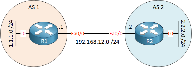
Imagine you enable BGP on both routers and you put in the following command on the R1 router:
neighbor 192.168.12.2 remote-as 2
This will create a one way BGP neighbour relationship between R1 and R2. This means that if you enter the show ip bgp neighbors command on R1 you will see the neighbour relationship. If you go to R2 and enter the same command you will see no neighbours. Neighbours on the R2 router will appear once the following command has been entered on R2:
neighbor 192.168.12.1 remote-as 1
Once this is complete, then there is a mutual neighbour relationship.
The same thing occurs when you implement the topology in the lesson. When you put in the update-source lo0 command on one router, the neighbour relationship comes up in only one direction. If you go to the other router, you won’t see any neighbours until you put in the corresponding command in that router as well.
I hope this has been helpful!
Laz
1 Like
Hello Laz,
thanks for your detailed explanation, but my question is related to the last point you mentioned
The same thing occurs when you implement the topology in the lesson. When you put in the update-source lo0 command on one router, the neighbour relationship comes up in only one direction. If you go to the other router, you won’t see any neighbours until you put in the corresponding command in that router as well.
I have tried this again in a lab and the BGP neighborship formed successfully on both sides, although the update-source lo0 is configured from one side as shown below:
Router 1 side
R1#sh run | sec bgp
router bgp 1
 bgp log-neighbor-changes
 network 1.1.1.1 mask 255.255.255.255
 neighbor 2.2.2.2 remote-as 1
 neighbor 2.2.2.2 update-source Loopback0
R1#sh ip bgp summary | b Nei
Neighbor        V           AS MsgRcvd MsgSent   TblVer  InQ OutQ Up/Down  State/PfxRcd
2.2.2.2         4            1      10      12        2    0    0 00:05:54        0
Router 2 side
R2#sh run | sec bgp
router bgp 1
 bgp log-neighbor-changes
 neighbor 1.1.1.1 remote-as 1

R2#sh ip bgp summary | b Nei
Neighbor        V           AS MsgRcvd MsgSent   TblVer  InQ OutQ Up/Down  State/PfxRcd
1.1.1.1         4            1       5       6        5    0    0 00:01:55        1
and my question is why the bgp neighborship forms before adding the update-source lo0 on the second router although the neighbor statement is configured with the loopback ip address of the peer router?
Thanks
Walid
Hi Walid,
This will work as long as R1 is the router that initiates the TCP connection for BGP. It uses the IP address from the update-source command as the source (1.1.1.1) to initiate the connection and 2.2.2.2 as the destination. R2 responds with its 2.2.2.2 address.
When R2 initiates the connection, it uses the IP address on the interface that faces R1 (192.168.12.2) which doesn’t match the neighbor command on R1.
A quick way to verify that R1 is the TCP client is to look at the port numbers:
R1#show ip bgp neighbors | include port:
Local host: 1.1.1.1, Local port: 28823
Foreign host: 2.2.2.2, Foreign port: 179
R2#show ip bgp neighbors | include port:
Local host: 2.2.2.2, Local port: 179
Foreign host: 1.1.1.1, Foreign port: 28823You can see this in action in wireshark. Take a look at this capture:
I did a clear ip bgp * on R2. In packet 6, you can see that R2 did an attempt from 192.168.12.2 that R1 refuses in packet 7. When R1 initiates it from R1, it works.
Hope this helps!
Rene
1 Like
Rene,
Is it work if you use network command to advertise Loopback address at both pee routers under BGP instead of using static routes. Please explain in brief.
Thank you in Advance.
Hello Durga
The static routes to the loopback addresses are used in order to be able to establish BGP neighbor adjacency. If you don’t have neighbor adjacency, then even if you add the network command with the loopback addresses, the router will not share this information because there is no BGP neighbor.
The static routes in this scenario are necessary in order to establish BGP neighbourhoodship. These routes could be learned via an IGP as well, but for the sake of simplicity, it was done with static routes here.
I hope this has been helpful!
Laz
Hi Renee,
In your configs for static routes you use the specific IP address.. that does not seem to work.
!
ip route 192.168.23.3 255.255.255.255 192.168.12.2
!
I could not ping using that configuration for static routes. instead I went ahead and changed it to:
!
ip route 192.168.23.0 255.255.255.0 192.168.12.2
!
which was subnet, mask and then the IP. I was doing this on 7200 GNS3 virtual router OS:
R1#show version
Cisco IOS Software, 7200 Software (C7200-ADVENTERPRISEK9-M), Version 12.4(24)T5, RELEASE SOFTWARE (fc3)
Technical Support: http://www.cisco.com/techsupport
Copyright (c) 1986-2011 by Cisco Systems, Inc.
Compiled Fri 04-Mar-11 06:49 by prod_rel_team
ROM: ROMMON Emulation Microcode
BOOTLDR: 7200 Software (C7200-ADVENTERPRISEK9-M), Version 12.4(24)T5, RELEASE SOFTWARE (fc3)
What was interesting, and note I am a bit rusty on my static routing as I don’t use it much, was that after I fixed using subnet I could ping from R1 to R2 and even hit R2 192.168.23.1 but when I pinged from R1 to 192.168.23.3 which was R3 the ping got there but no response was found.
I would have thought that since R3 also had a static route for the subnet of 192.168.12.0 255.255.255.0 which it used to go out the R2 interface which was 192.168.23.1 that it should have had a return path.
R1:
C 192.168.12.0/24 is directly connected, FastEthernet0/0
192.168.23.0/24 is variably subnetted, 2 subnets, 2 masks
S 192.168.23.3/32 [1/0] via 192.168.12.2
S 192.168.23.0/24 [1/0] via 192.168.12.2
R1#
R2:
C 192.168.12.0/24 is directly connected, FastEthernet0/0
C 192.168.23.0/24 is directly connected, FastEthernet1/0
R2#
R3:
192.168.12.0/24 is variably subnetted, 2 subnets, 2 masks
S 192.168.12.0/24 [1/0] via 192.168.23.2
S 192.168.12.1/32 [1/0] via 192.168.23.2
C 192.168.23.0/24 is directly connected, FastEthernet0/0
R3#
Also my BGP is in active state which is bad of course so its not able to connect across there as well. Just in case of glitch I deleted the project and recreated it but having same issue.
R1#show ip bgp
R1#show ip bgp summary
BGP router identifier 192.168.12.1, local AS number 1
BGP table version is 1, main routing table version 1Neighbor V AS MsgRcvd MsgSent TblVer InQ OutQ Up/Down State/PfxRcd
192.168.23.3 4 3 0 0 0 0 0 never Active
R1#
and R3 nothing as well:
R3#show ip bgp
R3#show ip bgp summary
BGP router identifier 192.168.23.3, local AS number 3
BGP table version is 1, main routing table version 1Neighbor V AS MsgRcvd MsgSent TblVer InQ OutQ Up/Down State/PfxRcd
192.168.12.1 4 1 0 0 0 0 0 never Active
R3#
Here is the basic template that comes on this GNS3 router minus what I changed from the lesson. I don’t see anything unusual but maybe someone else will catch something here.
R1#show running-config
Building configuration…Current configuration : 1167 bytes
!
upgrade fpd auto
version 12.4
service timestamps debug datetime msec
service timestamps log datetime msec
no service password-encryption
!
hostname R1
!
boot-start-marker
boot-end-marker
!
logging message-counter syslog
!
no aaa new-model
ip source-route
no ip icmp rate-limit unreachable
ip cef
!
!
!
!
no ip domain lookup
no ipv6 cef
!
multilink bundle-name authenticated
!
!
!
!
!
!
!
!
!
!
!
!
!
!
!
!
archive
log config
hidekeys
!
!
!
!
!
ip tcp synwait-time 5
!
!
!
!
interface FastEthernet0/0
ip address 192.168.12.1 255.255.255.0
duplex half
!
router bgp 1
no synchronization
bgp log-neighbor-changes
neighbor 192.168.23.3 remote-as 3
neighbor 192.168.23.3 ebgp-multihop 2
no auto-summary
!
ip forward-protocol nd
ip route 192.168.23.0 255.255.255.0 192.168.12.2
ip route 192.168.23.3 255.255.255.255 192.168.12.2
no ip http server
no ip http secure-server
!
!
!
no cdp log mismatch duplex
!
!
!
!
!
!
control-plane
!
!
!
!
!
!
!
gatekeeper
shutdown
!
!
line con 0
exec-timeout 0 0
privilege level 15
logging synchronous
stopbits 1
line aux 0
exec-timeout 0 0
privilege level 15
logging synchronous
stopbits 1
line vty 0 4
login
!
endR1#
here is the pings which should work as far as I can tell. I did just rebuild my gns3 server since the upgrade came out I deleted the old one out as my upgrade did not work so had to reinstall everything new again.
R1#ping 192.168.23.1
Type escape sequence to abort.
Sending 5, 100-byte ICMP Echos to 192.168.23.1, timeout is 2 seconds:
!!!
Success rate is 100 percent (5/5), round-trip min/avg/max = 8/23/44 ms
R1#ping 192.168.23.3Type escape sequence to abort.
Sending 5, 100-byte ICMP Echos to 192.168.23.3, timeout is 2 seconds:
…
Success rate is 0 percent (0/5)
R1#
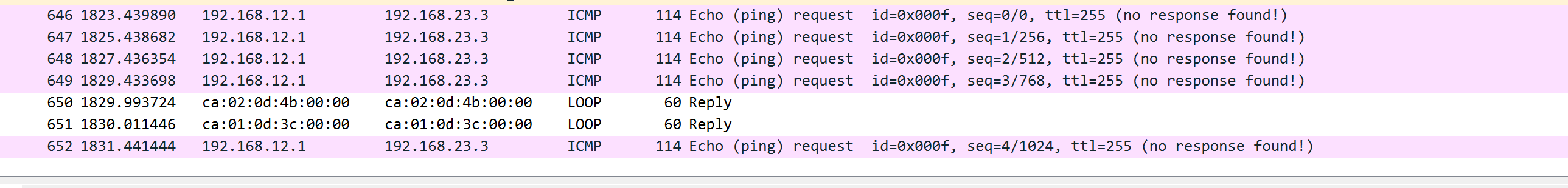
from the wireshark you see its saying it does not have a return path which is common thing but we have static routing it should be pushed out the IP we tell it to go and from there R2 which is a router should route it from the 23 over to the 12 or vice versus.
ah ok I have found the two issues here.
-
cannot use the specific IP in static route need to have network, mask, and then the ip interface that it heads out of. Perhaps in different OS versions you could use the specific but not on the majority. I have tested this on two different versions.
-
the second issue is in your configurations on R2 configuration you name the interface 192.168.23.1 yet when you do routing on R3 your ip route command you have that interface mislabeled as 192.168.23.2… which you do not use the dot 2 notation on R2 or R3 you only use .1 and .3.. so that explains why the static route does not work. the configuration has an error.
ah feels good to find the error funny how sometimes go to bed wake up and something stands out immediately where as you never saw it the evening before.
So anyway you will want to fix the typo error in the configurations!
================================================
I still cannot figure out why I cannot ping from R1 to R3 still looking into that and looking at different static labs to see if I can figure that out.
---------------- ah ok I figured that out to. Basically even though I had added the correct type of static route subnet, mask, and specific IP I had not removed the originally one and had left it there. It was messing with the route once I removed the specific IP static route everything started working:
R1(config)#no ip route 192.168.23.3 255.255.255.255 192.168.12.2
R1(config)#end
R1#
*Jul 11 12:49:58.766: %SYS-5-CONFIG_I: Configured from console by console
R1#ping 192.1168.
*Jul 11 12:50:01.530: %BGP-5-ADJCHANGE: neighbor 192.168.23.3 Up
Hello Brian
Yes, thanks for catching that. Yes, in the first set of configs, the R2 device has the following:
!
interface fastEthernet1/0
 ip address 192.168.23.1 255.255.255.0
!
when it should be this:
!
interface fastEthernet1/0
 ip address 192.168.23.2 255.255.255.0
!
Thanks and I’ll let Rene know…
Also, thank you for sharing your thought process with us, both your problems as well as the solutions that you have discovered.
Laz
It has been fixed. Thanks @wilder7bc
HI,
"If we Source eBGP from the loopback interfaces then we need multihop ".
I really did not get the idea where do we need to do use these kind of setup .
Thanks
Hello Sims
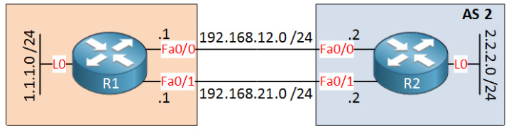
Whenever you have a scenario where you have multiple connections between routers such as the following, you have two choices.
One choice is to use the IP address of one of the interfaces for the eBGP source, such as 192.168.12.1 of R1. The problem is that if this link fails, the neighbourhoodship between the two routers fails. This means that the backup link cannot be used, and is essentially useless.
Now a solution to this is to create a loopback interface with an address of 1.1.1.1 and configure it as the source for eBGP. If this happens, then even if one of the links goes down, .1.1.1.1 is reachable via the second link and thus eBGP functions, and the backup will operate correctly.
Now the problem is that eBGP will only create BGP neighbor relationships with directly connected routers. The loopback interface of R1 is not directly connected to R2 so no neighbour relationship will form.
EXCEPT if we use the multihop command which indicates to eBGP that in order to reach the neighbor, you must go through several hops. Now from the Loopback interface, connectivity to the R2 device goes through two routers, the first being R1 itself.
Now it’s a good idea to use the loopback on both ends, so that would mean that the hop count increases even more for one loopback to reach the other. If directly connected is considered a hop count of 0, then adding two loopbacks would bring that up to a hopcount of 2 to reach each other. That makes sense since there are two routers between the two loopbacks.
I hope this has been helpful!
Laz
1 Like
Hi Lazaros,
Why do you say "if we use the fastEtherent interfaces, and one link goes down, then the BGP connection between them will also go down, thus rendering the redundant link unusable. "? The static routes have been set, plus, advertisements have been made for the networks. Why would one link of the two brings both down if it goes down?
Apart from load-sharing, isn’t it also being used for redundancy? what is the use then?
Thanks in advance. ![]()
Hello Mohammud
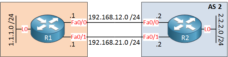
Let’s use this diagram for the purposes of explanation.
Let’s say we used the 192.168.12.1 IP address of R1 and the 192.168.12.2 IP address of R2 to create the neighbour relationship between the routers. R1 and R2 exchange information via BGP and use both links for traffic.
Now imagine that interface Fa0/0 on R1 goes down. That’s OK cause we have redundant links therefore traffic will use the other link, right? Wrong. Because the IP address of Fa0/0 has been used to create the neighbour relationship, this IP is no longer active, and thus the BGP neighbour relationship fails. Any redundant routing also fails, therefore the redundant link is unusable.
This is the reason why it is best practice to use loopback addresses to create neighbour relationships in BGP. If the Fa0/0 goes down, the loopback interface would still be up, thus the BGP neighbour relationship would still be active, and redundancy would kick in.
The point I was trying to make is that we shouldn’t use the IP address of a physical interface for BGP neighbour relationships. Otherwise, such redundancy would not function correctly.
I hope this has been helpful!
Laz
2 Likes
Thanks Lazaros for the effort. It is now clearer ![]()
1 Like
Blockquote
Even though R1 and R3 are now neighbors, having a non-BGP in router in between R1 and R3 is a bad idea. R1 and R3 might exchange prefixes through BGP but once packets reach R2, it will have no clue where to forward these packets to…
Blockquote
What if we were to use a GRE tunnel destination IP as a neighbor to peer with to make it look like the two AS are directly connected to each other? Will that work?
Hello Mark
Actually what you suggest is a valid and often used technique. When you have two routers that are not directly connected but are in the same AS, and you want them to be BGP peers, you can indeed create a GRE tunnel between those routers. Keep in mind however, that this is recommended more for iBGP, that is, having both routers in the same AS. For eBGP, creating a GRE tunnel over an AS boundary can be awkward and involves other issues that can make such a configuration complicated.
I hope this has been helpful!
Laz