How to configure IPv6 Static Route

I built this, and it works perfectly. What version of IOS are you using with GNS3 for this?

I am noticing some difference in output. For example, my router A for show ipv6 route produces this:

S   ::/0 [2/0]
     via FE80::C, FastEthernet0/0
C   2001:DB8:3C4D:1::/64 [0/0]
     via FastEthernet0/0, directly connected
L   2001:DB8:3C4D:1:C801:29FF:FE78:0/128 [0/0]
     via FastEthernet0/0, receive
L   FF00::/8 [0/0]
     via Null0, receive

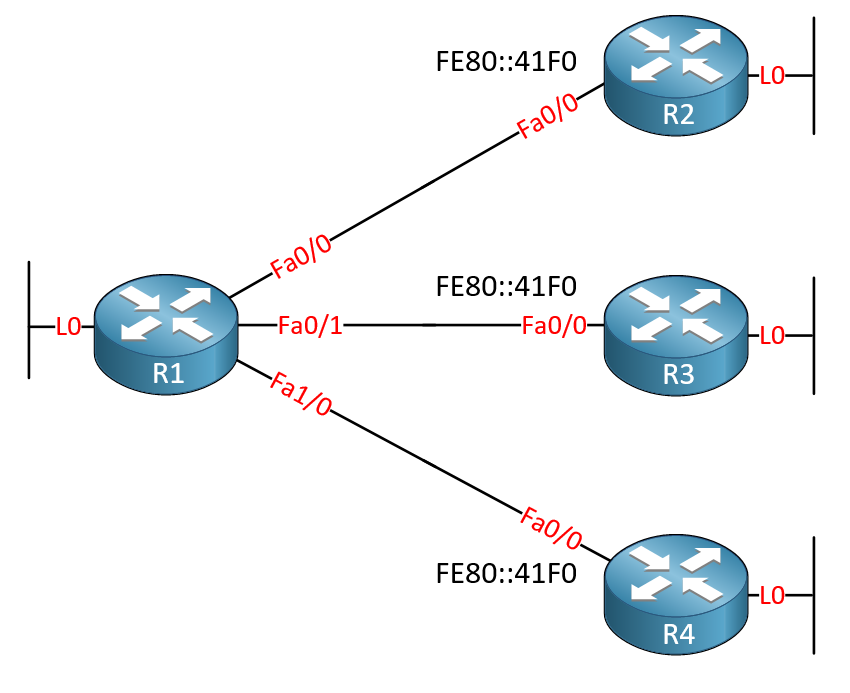
Notice how for the default static route, mine says “via FE80::C, FastEthernet0/0” where yours just lists the interface. By the way, I hard coded FE80::C on both of Router C’s links.

Let’s make this simple and focus on only A, C, and D. Here is the show run I have for all of them:

A

!
upgrade fpd auto
service timestamps debug datetime msec
service timestamps log datetime msec
no service password-encryption
!
hostname A
!
boot-start-marker
boot-end-marker
!
logging message-counter syslog
!
no aaa new-model
ip source-route
no ip icmp rate-limit unreachable
ip cef
!
!
!
!         
no ip domain lookup
no ipv6 cef
!
multilink bundle-name authenticated
!
!
!
!
!
!
!
!
!
!
!
!
!
!
!
!
archive
 log config
  hidekeys
! 
!
!
!
!
ip tcp synwait-time 5
ip ssh version 1
!
!
!
!
interface FastEthernet0/0
 no ip address
 duplex half
 ipv6 address autoconfig
 ipv6 enable
!
ip forward-protocol nd
no ip http server
no ip http secure-server
!
!
!         
no cdp log mismatch duplex
!
!
!
!
!
!
control-plane
!
!
!
!
!
!
!
gatekeeper
 shutdown
!
!
line con 0
 exec-timeout 0 0
 privilege level 15
 logging synchronous
 stopbits 1
line aux 0
 exec-timeout 0 0
 privilege level 15
 logging synchronous
 stopbits 1
line vty 0 4
 login
!
end

C

upgrade fpd auto
service timestamps debug datetime msec
service timestamps log datetime msec
no service password-encryption
!
hostname C
!
boot-start-marker
boot-end-marker
!
logging message-counter syslog
!
no aaa new-model
ip source-route
no ip icmp rate-limit unreachable
ip cef
!
!
!
!         
no ip domain lookup
ipv6 unicast-routing
ipv6 cef
!
multilink bundle-name authenticated
!
!
!
!
!
!
!
!
!
!
!
!
!
!
!
!
archive
 log config
  hidekeys
! 
!
!
!
!
ip tcp synwait-time 5
ip ssh version 1
!
!
!
!
interface FastEthernet0/0
 no ip address
 duplex auto
 speed auto
 ipv6 address FE80::C link-local
 ipv6 address 2001:DB8:3C4D:1::1/64
 ipv6 enable
!
interface FastEthernet0/1
 no ip address
 duplex auto
 speed auto
 ipv6 address FE80::C link-local
 ipv6 address 2001:DB8:3C4D:2::1/64
 ipv6 enable
!
ip forward-protocol nd
no ip http server
no ip http secure-server
!
!
!
no cdp log mismatch duplex
!
!
!
!
!
!
control-plane
!
!
!
!         
!
!
!
gatekeeper
 shutdown
!
!
line con 0
 exec-timeout 0 0
 privilege level 15
 logging synchronous
 stopbits 1
line aux 0
 exec-timeout 0 0
 privilege level 15
 logging synchronous
 stopbits 1
line vty 0 4
 login
!
end

D:

upgrade fpd auto
service timestamps debug datetime msec
service timestamps log datetime msec
no service password-encryption
!
hostname D
!
boot-start-marker
boot-end-marker
!
logging message-counter syslog
!
no aaa new-model
ip source-route
no ip icmp rate-limit unreachable
ip cef
!
!
!
!         
no ip domain lookup
no ipv6 cef
!
multilink bundle-name authenticated
!
!
!
!
!
!
!
!
!
!
!
!
!
!
!
!
archive
 log config
  hidekeys
! 
!
!
!
!
ip tcp synwait-time 5
ip ssh version 1
!
!
!
!
interface FastEthernet0/0
 no ip address
 duplex half
 ipv6 address autoconfig
 ipv6 enable
!
ip forward-protocol nd
no ip http server
no ip http secure-server
!
!
!         
no cdp log mismatch duplex
!
!
!
!
!
!
control-plane
!
!
!
!
!
!
!
gatekeeper
 shutdown
!
!
line con 0
 exec-timeout 0 0
 privilege level 15
 logging synchronous
 stopbits 1
line aux 0
 exec-timeout 0 0
 privilege level 15
 logging synchronous
 stopbits 1
line vty 0 4
 login
!
end

This particular lab whose topology is displayed above was built in packet tracer 6.1 using ios Version 15.1(4)M4. I noticed you hard code the link local address. And I also noticed that your static route is sending all traffic to the Link local address of router C. Is that why mine is not working? Can you explain why I have to use the link local address of Router C instead of the interface address. Appreciate your feedback. I will make some configuration changes and see if I can reproduce your results.

I hard coded the LL address of C for two reasons: 1) to make it easier to read, and 2) it is a Cisco best practice to hard code LL addresses.

Even though I did that, it is not necessary.

As far as the static addresses having the LL address of C as the destination, that is what auto-config does on its own, when you enable ipv6 autoconfig on the A,B,D,and E routers.

The key command to this whole lab is on C where you must have “ipv6 unicast routing”

Thank you so much for your assistance. I hard code the link local address as you suggested or did and I was able to route from a/b routers to d/e routers. Awesome work. Thank you so much.

Awesome–I am glad you got it working

19 posts were merged into an existing topic: How to configure IPv6 Static Route

Hi,
I have one question,

  1. If I am getting IPv6 from DHCP server on router interface same as IPv4 ISP. Then How I configure my default route to point ISP? Because I don’t have any information about ISP?
    Plz Help.
    Regards,
    Deepak Kumar

Hello Deepak

If I understand your question correctly, you have an ISP that is providing you with an IPv6 address on your edge device dynamically. At the same time, you are also getting an IPv4 address on the same interface. Correct? If so, there are two ways to get a default route:

  1. Either via the DHCP information that you have received, which should include a default gateway
  2. By communicating with your ISP to find out what the next hop IP address is.

I hope this has been helpful!

Laz

Ok first question. In you post you have the following below. YOu will notice its pointing to :2:2 however there is no :2:2 network on any of the routers is this a typo did you mean to say :23:23::??? also its a 64 instead of a 128 which is what the loopback is. However maybe all addresses are held within the 128?? So your just pointing to a non-existent address knowing that since the one is a prefix of 128 that can hold all addresses so its being sent that way. very cryptic though and I wanted to confirm.

if this is just a typo then you might want to fix that one and the one below it to as both refer to a :2:2 where none exist.

Capture

also my follow up question is this. a floating route just means you have two static routes and if one goes down there is another one so that is called a floating static route?

Hello Brian

It seems that @ReneMolenaar is using the 2001:2:2::/64 prefix for the L0 interface on R2 in the first diagram, but when he adds R3 to the topology, he changes it to 2001:23:23::/64. I’ll let him know to change it so that it is consistent all the way through the lesson, either 2:2 or 23:23, including the routing tables.

Yes. A floating static route is essentially a backup route that is statically configured to have a higher administrative distance than the primary route. This primary route can be a static route as well, or a dynamically configured route. It is the backup static route that is referred to as the floating static route. Note that this is a concept that is used in both IPv4 and IPv6 networks.

I hope this has been helpful!

Laz

1 Like

Beautiful :slight_smile:

1 Like

Hello @lagapidis

Could you please explain why this happens? I just tried to lab it out (using F0/0) and it didn’t work as well

“Just like with IPv4, it is possible to use an interface as the next hop. This will only work with point-to-point interfaces, If you try this with a FastEthernet interface, you’ll see that the router will accept the command but the ping won’t work. You can’t use this for multi-access interfaces.”

Hello Sales

It is generally not a good idea to configure default route using only physical interface as next-hop if this physical interface is NOT point-to-point. For example its NOT good to use physical interface as nex-hop if it is an Ethernet interface, because ethernet is broadcast multi access by its nature.

I suggest you to do small lab about it, it will let you grasp the concept.
Lets say you have small topology, two inter-connected routers with a few loopbacks configured on them, to simulate networks. Configure loopbacks and link connecting R1 and R2.

topology

Just in case you was playing around with pings do the following on both routers.
Disable ip cef
R1 & R2 (config)# no ip cef

Disable route-cache
R1 & R2 (config)# interface g0/0
R1 & R2 (config-if)# no ip route-cache
(now all packets are process-switched)

Disable proxy ARP
R1 & R2 (config)# ip arp proxy disable

Make sure that there are not any additional ARP entries, it should look like this

R1# show ip arp
Protocol  Address          Age (min)  Hardware Addr   Type   Interface
Internet  12.12.12.1              -   0ccb.bdce.9e00  ARPA   GigabitEthernet0/0

R2# show ip arp
Protocol  Address          Age (min)  Hardware Addr   Type   Interface
Internet  12.12.12.2              -   0ccb.bd3c.9200  ARPA   GigabitEthernet0/0

If you have additional entries in ARP cache, then delete this entries by
R1 or R2# clear ip arp <ip_entry>

Now, on R1 create default route using ethernet interface as next-hop.

R1(config)# ip route 0.0.0.0 0.0.0.0 gigabitEthernet 0/0
%Default route without gateway, if not a point-to-point interface, may impact performance

New IOS system should give you this warning.

As next, go on R2 and create default route using ip address as next-hop.

R2(config)# ip route 0.0.0.0 0.0.0.0 12.12.12.1

IOS system should be satisfied, not generating any warning message.

Do some pings from R2 towards R1 loopbacks.

R2# ping 1.1.0.1
R2# ping 1.1.1.1
R2# ping 1.1.2.1
R2# ping 1.1.3.1

All pings should be successfull. (To be honest, these pings are successfull only because R2 will use its g0/0 ip address as source of these pings, ip of outgoing interface and that ip is in range of dirrectly connected network for R1. If you will ping with ip source address of any of R2 loopbacks, these pings will fail. Example “ping 1.1.0.1 source 2.2.0.1” will fail.)

Check out ARP table of R2.

R2# show arp
Protocol  Address          Age (min)  Hardware Addr   Type   Interface
Internet  12.12.12.1              1   0ccb.bdce.9e00  ARPA   GigabitEthernet0/0
Internet  12.12.12.2              -   0ccb.bd3c.9200  ARPA   GigabitEthernet0/0

Do some pings from R1 to R2 loopbacks.

R1# ping 2.2.0.1
R1# ping 2.2.1.1
R1# ping 2.2.2.1
R1# ping 2.2.3.1

All pings should fail.

Check out ARP table of R1.

R1# show arp
Protocol  Address          Age (min)  Hardware Addr   Type   Interface
Internet  2.2.0.1                 0   Incomplete      ARPA   
Internet  2.2.1.1                 0   Incomplete      ARPA   
Internet  2.2.2.1                 0   Incomplete      ARPA   
Internet  2.2.3.1                 0   Incomplete      ARPA   
Internet  12.12.12.1              -   0ccb.bdce.9e00  ARPA   GigabitEthernet0/0
Internet  12.12.12.2              7   0ccb.bd3c.9200  ARPA   GigabitEthernet0/0

As you see, Hardware Addr (MAC) of next-hop is Incomplete, because ethernet is multi-access it was not able to recognize MAC of next-hop. Interface was not identified, Interface row is empty.

Lets go further and help R1 with his default route issue. Go on R2 and enable Proxy ARP there.
R2(config)# no ip arp proxy disable

Now try pings from R1 towards R2 loopbacks.

R1# ping 2.2.0.1
R1# ping 2.2.1.1
R1# ping 2.2.2.1
R1# ping 2.2.3.1

All pings are working now, everything looks Gucci.

Check R2 ARP table. Remember that we used default “ip route 0.0.0.0 0.0.0.0 12.12.12.1”, next hop specified with IP.

R2# show arp
Protocol  Address          Age (min)  Hardware Addr   Type   Interface
Internet  12.12.12.1              6   0ccb.bdce.9e00  ARPA   GigabitEthernet0/0
Internet  12.12.12.2              -   0ccb.bd3c.9200  ARPA   GigabitEthernet0/0

That looks good.

Check R1 ARP table. We used default route “ip route 0.0.0.0 0.0.0.0 g0/0”, next hop specified with outgoing interface.

R1# show arp
Protocol  Address          Age (min)  Hardware Addr   Type   Interface
Internet  2.2.0.1                 0   0ccb.bd3c.9200  ARPA   GigabitEthernet0/0
Internet  2.2.1.1                 0   0ccb.bd3c.9200  ARPA   GigabitEthernet0/0
Internet  2.2.2.1                 0   0ccb.bd3c.9200  ARPA   GigabitEthernet0/0
Internet  2.2.3.1                 0   0ccb.bd3c.9200  ARPA   GigabitEthernet0/0
Internet  12.12.12.1              -   0ccb.bdce.9e00  ARPA   GigabitEthernet0/0
Internet  12.12.12.2             11   0ccb.bd3c.9200  ARPA   GigabitEthernet0/0

Pay attention to Hardware Addr (next hop MAC). There are total 5 entries that have same next hop MAC, that is kinda waste of resources. Do you see that danger lurking behind our back? :sunglasses:

1 Like

Hello sales2161

@fugazz’s is quite complete, let me add my two cents as well :stuck_out_tongue:

If you look at the following diagram, you can see we have four routers connected to the same network segment via an L2 switch:
image

Let’s assume that R1 is configured with a route to Network B that is statically configuring using only an exit interface of G0/0. If a packet is sent from Network A with a destination of Network B, the router will look at the routing table, will know the exit interface, but will not know what MAC address to place in the destination field of the frame. There are three possibilities, none of which can be known. Such a configuration would fail.

If the route were configured using an next hop IP address, R1 would either look up the MAC address of the next hop from its ARP table, or, it would send out an ARP request to obtain it, thus encapsulating the frame with the appropriate MAC of the router to which the packet should be sent.

Technologies such as serial connections that are point to point in nature, don’t actually use Layer 2 source and destination addresses (such as MACs for Ethernet), so an exit interface in the static route is sufficient.

I hope this has been helpful!

Laz

2 Likes

Hey Rene,

I know this is an older thread but I noticed an issue with the topology picture in the floating section, are both loopbacks supposed to have the same IPv6 address? Based on your explanation below, it looks like lo0 on r2 should have an address in the ::2:2/128 range, is this correct? Loving the content so far!

Hello Kyle

The same IPv6 address is assigned to both loopbacks on purpose. You wouldn’t typically apply such a configuration in a production network, however, for the purposes of the lesson, it is indeed valid. From the point of view of R1, such a topology is the same as this:

Now, this topology would be used in a production network. But again, this changes nothing from the point of view of R1, and the point of the lesson is to learn how to configure the routing for R1.

I hope this has been helpful!

Laz

I am a bit confused

You said the router dose not know the interface of the link local address so we have to tell it. Why exactly is that? My understanding would be the route table would be aware of the link local addresses so why can it not figure out the interface like a global unicast address can?

Hello Patrick

In the lesson, Rene states the following:

When you use a global unicast address as the next hop, your router can look at the routing table and figure out what outgoing interface to use to reach this global unicast address. With link-local addresses, the router has no clue which outgoing interface to use so you will have to specify both the outgoing interface and the link-local address.

The reason for this is the fact that a link-local address must be unique only within the network segment it belongs to. That means I can use the same link-local address on all the interfaces of my router. Or, I can assign the same link-local address to all of the neighboring routers. So there is no guarantee that a particular link-local address will point to only one next-hop router. Take a look at the following diagram:

This is a valid setup with the same link-local address on the Fa0/0 interfaces of all three routers. So there is no way to uniquely identify a link-local address with a particular exit interface on R1 to reach such an address.

Secondly, link-local addresses are not routable, therefore, they don’t appear within the routing table as destinations. They do appear as next-hop addresses but never as destinations to reach.

Let’s say I had a routing table entry like so, without the exit interface. What would happen?

R1(config)#ipv6 route 2001:DB8:2:2::/64 FE80::41F0

Well, if R1 received a packet with a destination IPv6 address of 2001:DB8:2:2::1, it would look it up in the routing table and find this entry. It would then take a look at the next hop IP. It must, however, find the exit interface. How? It will do a recursive lookup of the FE80::41F0 address. However, it will not find it in the routing table. because link-local addresses are not routable. Therefore the packet will be dropped.

For all of these reasons, using the link-local address as the next hop without specifying an exit interface will fail. You must specify the exit interface along with the link-local next hop address.

I hope this has been helpful!

Laz

1 Like

Hallo Rene and Laz,

In Section 1.4.2 and 1.4.3:

R1(config)#ipv6 route 2001:DB8:2:2::/64 2001:DB8:12:12::2 2
R1(config)#ipv6 route 2001:DB8:2:2::/64 Serial 0/0/0 FE80::21C:F6FF:FE11:41F0 2

What network is 2001:DB8:2:2::/64 because, when R3 was added in the topology, the network we are to reach is 2001:DB8:23:23::/64. 2001:DB8:2:2::/64 was when we had routers R1 and R2.

Thanks for the wonderful work done.

Joyce

Hello Joyce

That should actually be 2001:DB8:23:23::/64 for both sections 1.4.2 and 1.4.3. Thanks for pointing that out. I will let Rene know to make the correction.

Thanks again!

Laz