So helpful as always thank you so much Lazaros
1 Like
Hello Vadim
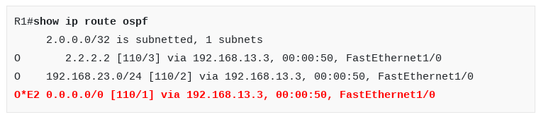
When using the default-information originate command in OSPF, you have several options:
default-information originate [always] [metric metric-value] [metric-type type-value] [route-map map-name]
Here you can see that you can specify the metric as well as the metric type. By default, the metric type is E2 and the metric value is 1 and this is why you see this output in the routing table. You can find out more info about how OSPF generates default routes and what default metrics it assigns them at this Cisco documentation. For more info about the metric type E2 and what it means, you can see the following lesson:
I hope this has been helpful!
Laz
Hi Rene,
I am practicing OSPF in packet tracer, some of the commands don’t work as:
-
when I am trying to do
debug ip ospf packetthen there is no output, instead there are only 2 sub-options available which are “adj” & “events” underdebug ip ospfcommand. -
the command
default-information originate alwaysis not working (also there is no default route created in the routing table).
But when I run this commanddefault-information originate, the output is:
21:26:45: OSPF: Build router LSA for area 0, router ID 3.3.3.3, seq 0xffffffff80000035
Please help…
Hello Akansh
Unfortunately, Packet Tracer does not have all of the available commands that a real Cisco IOS device would have. Specifically, the debug capability of packet tracer routers will only debug OSPF events and OSPF adjacency events. It is not possible to display OSPF packet debugs.
Similarly, the always keyword for the default-information originate command is not available in Packet Tracer.
With the topology in the lesson, if you were to issue the default-information originate command on R2, nothing would change. This is because this command, without the always keyword would cause R2 to send a default route via OSPF to the other two routers only if a default route existed in its routing table. Since no default route is configured, there are two solutions. The first is to use the always keyword. The second, which you can do on Packet Tracer, is to create a static default route in your routing table. To do this, you can create a loopback interface, and then issue the command:
ip route 0.0.0.0 0.0.0.0 loopback 0
This will place a default route in the routing table which will then be shared using OSPF with other OSPF routers.
Now this default route will not actually do anything in this scenario, since a loopback cannot route traffic elsewhere, but the point here is that the default route was propagated to other OSPF routers. In a real-world environment, the default route would be configured to send traffic to another interface that connects to the Internet.
I hope this has been helpful!
Laz
Hi,
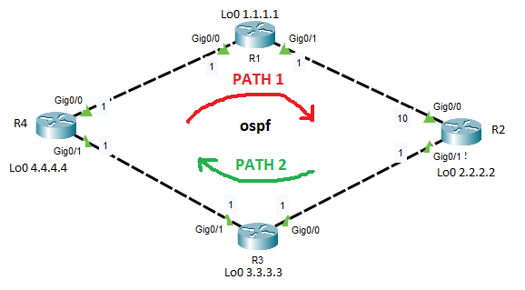
diagram is an ospf network and the are cost are as in the diagram.
R2 interface g0/0 cost is manually configure to 10.
- please correct if i’m wrong:
when ping from R4 to R2, traffic will travel using path 1 and return using path 2 because of the modified cost. - How to check the path from R4 travelling to R2, and return path from R2 to R4, if i dont have privilege to access R2? Any specific command, i tried trace route but it not showing return path.
thanks
Hello Izuone
When OSPF determines the cost to a particular destination, it calculates a cumulative cost to that destination. This cumulative cost is the sum of all outgoing interface costs along that route. In your particular topology, traffic from 4.4.4.4 to 2.2.2.2 will actually be load balanced across both links because the cost is the same for Path1 and Path2. This is because only outgoing interface costs are taken into account, and the Gig0/0 interface on R2 is an incoming interface for this traffic, so it wouldn’t be included in the cost calculation.
On the return trip, however, only Path2 would be chosen, because the cost of 10 is included in the sum of all outgoing interface costs, as Gig0/0 would be an outgoing interface in that direction of traffic flow.
For more information about equal-cost load balancing for OSPF, take a look at the last section of this lesson:
The best way to determine the path that was taken is to use traceroute. However, for traffic from R2 to R4, if you don’t have access to R2, then the only way to determine what path was taken is to use packet capture to see on which interface the return traffic comes in. There are several options for packet capturing including connecting a switch between R3 and R4 and using SPAN, or by using Cisco Embedded Packet Capture (EPC).
I hope this has been helpful!
Laz
What is the layer-2 MAC address is being used by OSPF for 224.0.0.5 & 6 ?
can you describe little bit about area 0.0.0.1 and area 1.How to write the area 321 in binary ??
Why OSPF treated loop-back as host IP ??
How Router ID effect the flooding procedure in OSPF in case 2 router have same router ID within an area or in a different area ??
Hello Narad
Take a look at this lesson:
Whether you write it as 0.0.0.1 or 1, the value used for the OSPF area is the same. It is simply a different notation. So 0.0.0.57 is the same as 57, and 0.0.1.255 is the same as 111111111 in binary, which is 511. To get 321 in dotted decimal you first conver to binary which is 101000001 and then convert to dotted decimal which is 0.0.1.65. Notice the following:
RouterA(config-router)#network 198.51.100.0 0.0.0.255 area ?
<0-4294967295> OSPF area ID as a decimal value
A.B.C.D OSPF area ID in IP address format
The range of values in decimal is the same as the number of values in a 32 bit dotted decimal notation.
Whether you use dotted-decimal or decimal, the router will interpret it as binary in the end, so it’s only a matter of notation.
If you have the same router ID in a different OSPF area, you have no problem, since routers in different areas never become neighbors, and thus will never share information with each other. However, if they are in the same area, you will have a problem because:
- OSPF routers with the same router ID will never become neighbors.
- Other OSPF routers can only create an adjacency with one of the two routers with the same router ID. You may find neighbor flapping taking place in some cases.
I hope this has been helpful!
Laz
there seems to be a mistake here:
R2#show ip ospf neighbor
Neighbor ID Pri State Dead Time Address Interface
192.168.13.1 1 FULL/BDR 00:00:31 192.168.12.1 Ethernet0/0
3.3.3.3 1 FULL/DR 00:00:38 192.168.23.3 FastEthernet1/0

R1#show ip ospf neighbor
Neighbor ID Pri State Dead Time Address Interface
3.3.3.3 1 FULL/BDR 00:00:33 192.168.13.3 FastEthernet1/0
2.2.2.2 1 FULL/DR 00:00:30 192.168.12.2 Ethernet0/0

R3#show ip ospf neighbor
Neighbor ID Pri State Dead Time Address Interface
192.168.13.1 1 FULL/DR 00:00:37 192.168.13.1 FastEthernet1/0
2.2.2.2 1 FULL/BDR 00:00:30 192.168.23.2 FastEthernet0/0
Isn’t it reversed?
Hello Nicolas
Actually, this looks correct. You can see that R2 sees two neighbors:
- 192.168.13.1 which is the router ID of R1, observed via a nnext hop address of 192.168.12.1, and off of the E0/0 interface, which does indeed connect to R1
- 3.3.3.3 which is the router ID of R3, observed via the next hop address of 192.168.23.3, off of Fa1/0, which connects to R3.
If you follow the same logic for the other two neighbor outputs, you’ll see that it is correct.
I hope this has been helpful!
Laz
Hi professor, when you mentioned about the loop back interface, can you please tell me what is the function of it and why we used this command.
R2(config)#interface loopback 0
R2(config-if)#ip address 2.2.2.2 255.255.255.0
Can some one help me clear this issue for me and where did the IP 2.2.2.2 came from, it is slightly confusing as it is not in the diagram
Hello Abdul
Take a look at this NetworkLessons Note that talks about loopback addresses.
In this particular case, the loopback was configured in order to see how the choice of the router ID for OSPF is made, and how it is affected by the creation of such a loopback interface.
I hope this has been helpful!
Laz
2 Likes
Thankyou @lagapidis, it is really helpful and now I understood. Can you please answer my recent query in Introduction to OSI model. I will tag you there. Thanks ![]()
1 Like
? Once you advertise the loop-back address, will all the networks be advertised? do I have to create an entry for every network?
Hello Carter
Simply advertising the loopback address does not cause all networks to be advertised. OSPF will advertise only the networks that are included under the network command. In the example in the lesson, the loopback address was advertised in much the same way that you would advertise the network of any physical interface on the device.
I hope this has been helpful!
Laz
1 Like
Hi everyone, new member here and very happy with the great content, thanks.
I have this same scenario, basically 2 multilayer switches connected via port-channel. Each switch has 3 SVIs for inter-vlan routing and they connect to the back bone router via routed link.
I was wondering if there is lesson that can clarify this, but I am confused about how SVIs work in OSPF. From the lessons, I understood OSPF works by creating relationship with directly connected neighbors. In fact the cost is based on the bandwidth of the physical link, correct? In this case both switches are connected to each other via physical interfaces, so why would they need to send “Hellos” over the SVI, which are logical interfaces.
I hope my explanation and question makes sense. I can always upload my topology if needed.
Thanks
Hello Joseph
SVIs on L3 switches act logically in the same way as physical ports do on routers. As far as OSPF goes, these ports participate in OSPF in the same way as their physical counterparts. Typically, an SVI acts as the default gateway for subnets that serve host devices. So network-design-wise, SVIs in such a situation will typically be configured as passive on the OSPF topology since they will have no other OSPF peering on that network segmet. If the SVIs do connect to another OSPF router then obviously they should remain active.
In your particular configuration, you have two L3 switches connected via a port channel, and a router connected to each of those switches with a routed port. If OSPF is configured on all three devices, and all networks are configured to participate, what role the SVIs will play in this scenario as far as OSPF is concerned, will depend upon the design.
If the portchannel is a Layer 3 port channel, then the connection between the two switches acts as if they were routers. That is, the port channel acts as if it is a routed port. If however that portchannel is operating at Layer 2 and is a trunk, then you can confgure the SVIs of on each swich to act as OSPF enabled ports creating an OSPF adjacency over each VLAN between the switches. What you will actually do depends upon the way in which you have deployed your two L3 switches, and what VLANs span the two switches, and also what kind of gateway redundancy (such as HSRP or VRRP for example) you may have configured.
Hellos will only be sent if the two switches are acting as OSPF neighbors. And you are correct, the cost s indeed based on the bandwidth of the physical link.
I’ve explained the various scenarios and how OSPF would be applied to them in very general terms. If you would like a more specific approach, feel free to share your topology and some more info about the configuration you have between the two switches so that we can more specifically address your particular scenario.
I hope this has been helpful!
Laz
Hi,
Can we up neighbor relationship between two routers which are not directly connected ? If we have R1-R2-R3, We need to have OSPF in between R1 and R3. If so, How we can do it ?
Hello ChaD
OSPF is designed to have adjacencies form between routers that are directly connected. One of the parameters that is checked when two directly connected OSPF routers initially attempt to create an adjacency, is the IP address and subnet mask of the interfaces through which that connection is taking place. In the initial Hello packet, the source OSPF router IP as well as the network mask are conveyed. If the IP addresses of the involved interfaces are in the same subnet, the adjacency takes place.
Having said that, there are cases where you would want to create an OSPF adjacency between OSPF routers that aren’t directly connected. However, to do this requires specific configurations and conditions. Some scenarios where this would be possible include:
- Virtual Links - Used to link an OSPF area to the backbone area (Area 0) through another area, ensuring continuous OSPF network connectivity even when direct physical links to the backbone are not available.
- GRE tunnels - You can interconnect two OSPF neighbors over a GRE tunnel. The routers believe they are directly connected, but their link is actually tunneled through multiple other devices.
- MPLS VPNs - OSPF can be used to form adjacencies over MPLS VPNs. This is commonly seen in enterprise networks where different branches are connected via an MPLS cloud.
I hope this has been helpful!
Laz