How to configure Policy Based Routing

Hello Qudama

If I have understood correctly, you want to apply policy-based routing (PBR) to this implementation. You mention about the subinterface of the portchannel1. However, I am not clear as to what you want to achieve, and what problem you are facing. Can you give us some more information about what you are trying to do, and what kind of behavior you are seeing on your device?

Thanks!

Laz

Hi i have question please answer me
Why using access-list with PBR not Prifix-list?
I know prifix-list is more powerful with (ge , le ) and it can do route filtering

But what is the othere reasons to use access-list not Prifix-list with PBR ?

Hello Mohamed

When applying policy-based routing, you can have the route map match either access lists or prefix lists. Which one you will choose depends upon what you want to achieve.

Using access lists gives you more granular control as you can specify specific hosts or ranges of addresses. You can also match source and destination IP addresses as well as Layer 4 protocols (TCP/UDP) and even Layer 4 ports.

Prefix lists are useful when you want to match particular subnets or ranges of subnets. If that is what you want to achieve, then it is preferable.

In general, access lists are used most often with PBR simply because of their granularity. Prefix lists are ā€œmore powerfulā€ only in the sense that you can define a whole series of subnets with very concise and efficient statements (rather than just a single range of IP addresses).

Ultimately, what you use comes down to what the policy routing you want to apply requires.

I hope this has been helpful!

Laz

Hi Rene ,

Iā€™d like to know, when we do the route-map PBR_R1 permit 10, if we have another sequence 20, should we add it too?

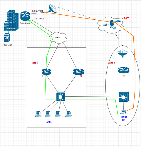
Hi Team, I have a question related to PBR. consider the below example
Site 1 : Router1(R1) and Router2 (R2)
site 2 : Router3 (R3)

site 1 Routers are in IBGP whenever R1 fails it falls back to R2.
Site 2: R3 has Vsat connectivity, however, all the Site 2 traffic is routed via Site 1, as the LAN of Site 2 has a direct cable connected to Site 1 via 6509 switches at Site 1 and Site 2.

Main HQ is a data center that has MPLS and VSAT links connected on different interfaces and the sites are connected to DC via MPLS(Site 1) and Vsat (site2)

Question: How to test the Site 2 vsat link via PBR

There is a host machine in site 2 that needs to reach the DC via site 2 vsat link . - how this can be achievable?

Assumptions:

  1. I can create PBR on Site 1 Lan interface of the R1 router as next hop ip as site 2 peer ip
    (The source is the host machine in Site 2 and the destination is a switch in Datacentre.)

when we apply PBR the Host traffic will reach the R1 Lan interface and reroutes the traffic to site2 vsat link peer ip and from there, it reaches the Datacentre via vsat link

what about the return traffic from the data center? which path it will choose we need the same vsat link to be used not the MPLS link in DC how to achieve this?

Hello David

It is possible to have multiple statements in a specific route map using the sequence numbers as you suggest. The route map in the lesson is this one:

R1(config)#route-map PBR_R1 permit 10
R1(config-route-map)#match ip address ICMP_R1
R1(config-route-map)#set ip next-hop 192.168.13.3

Letā€™s say you want to add a second statement that matches access list ICMP_R1a and you want to set the ip next-hop address to 192.168.12.2. You would add this second statement like so:

R1(config)#route-map PBR_R1 permit 20
R1(config-route-map)#match ip address ICMP_R1a
R1(config-route-map)#set ip next-hop 192.168.12.2

The result would be a single route map with multiple statements that are checked in sequence. If you took a look at the running config, you would see this route map shown as follows:

R1# show running-config
Building configuration...

Current configuration: 1325 bytes
!
!<-- output omitted - - >
!
route-map PBR_R1 permit 10
 match ip address ICMP_R1
 set ip next-hop 192.168.13.3
!
route-map PBR_R1 permit 20
 match ip address ICMP_R1a
 set ip next-hop 192.168.12.2
!

Each sequence appears as a separate entity in the configuration file, but all of it belongs to the same route map. Does that make sense?

I hope this has been helpful!

Laz

Hello Ravi

I tried creating a network topology on paper based on your description. The network is quite elaborate with multiple links between sites as well as to the internet and the DC. Your question was:

Keep in mind that PBR is a mechanism that can be used to define alternate routing paths in the event that the primary path fails. Thus, in your scenario/topology, there must be a primary path and a secondary path. If you simply want to have the host traffic routed via the VSAT link, simply configure routing to do so.

So, to be honest Iā€™m not sure where PBR comes into the picture. Are you suggesting that we use PBR to create an alternate path from that host to HQ via site 1 in the event of a failure? Via the direct link 6509 switches and via the MPLS connection from site 1 to the DC? If thatā€™s the case then you will have to perform your PBR at R3. I canā€™t get into details because it all depends upon the specific connectivity between devices, and that is not completely clear from your description. A network diagram would be helpful in this case.

Can you clarify with a diagram and an explanation of your primary path, and the desired alternate path that PBR can choose? Let us know so we can help you further!

I hope this has been helpful!

Laz

please find the high-level diagram

  1. All the Site 2 traffic is routed via Site 1. i want to have a quick test or generate traffic via vsat link i.e. connected on R3.
  2. I have a host machine H1 at SIte 2 if I want to route the H1 Traffic via VSAT link R3. how can be achieved please find below my assumptions
    a. Create PBR on the L3 switch of SITE 2 keeping the next hop as LAN ip of Router R3 for Host H1.
    b. If the traffic passes from the R3 via the VSAT link and reaches the datacentre, what would be the return path as MPLS has a lower AS path when compared to VSAT, how can I route return traffic via VSAT - ā€“ if i configure the static route on DC router pointing to H1 host via VSAT interface peer ip will it work?

Thanks
Ravi.

I have a Cisco ASR1001-X running IOS-XE 16.9.8E. This router is used to terminate a number of Tunnels to ZScaler nodes.
I have a new requirement to policy base route traffic to these tunnel interfaces. Documentation states I can set multiple next-hops ie the tunnel interfaces but I am unclear if this will load balanced or attempt to send all the traffic down the first address in the list. Is someone able to confirm the behaviour?

Hello Russell

When you set up multiple next-hops in a Policy-Based Routing (PBR) configuration, the Cisco router will not load balance the traffic among them. Instead, it will use the first valid next-hop in the list and send all the traffic to it.

The router will only move to the next next-hop in the list if the first one becomes unreachable. In other words, it works in a failover manner rather than load balancing.

However, if you want to distribute the traffic across multiple tunnel interfaces, you might want to consider using ECMP routing if your network design and requirements allow it. But this requires that you abandon the use of PBR. More about ECMP can be found at this NetworkLessons note.

I hope this has been helpful!

Laz

Hello Ravi

Thank you so much for the diagram, it makes perfect sense. You can create a PBR configuration in the L3 switch (Iā€™m assuming that H1ā€™s default gateway is an SVI on that L3 switch). You can use whatever parameters youā€™d like to cause traffic to be routed via R3. You can use the source IP address (that of H1) so that all of H1ā€™s traffic will be sent out of R3, or you can use specific destination addresses (such as the file server). That takes care of outgoing traffic. How can you ensure that the return traffic will take the same path?

First of all remember, if routing is successful in one direction this does not guarentee that it will be successful in the other direction. Nor does it mean that the same path is guarenteed to be taken.

To ensure return traffic takes the desired route, you can configure PBR on the DC1 router ensuring that packets with a destination of H1 are sent via the VSAT link. Alternatively, you can put in a static route to H1 which will essenially have the same results. Just make sure that all of the intervening routers will route such packets correctly. For example, make sure that R3 willl send any packets it reseives from/to H1 via the VSAT link and not back via the L3 switch, otherwise you may get a routing loop.

I hope this has been helpful!

Laz

1 Like

I am trying to implement policy based routing and I am seeing some strange results.
I was wondering if anyone had any ideas what the issues could be ?

The ā€œroutingā€ itself appears to be working as when I do ping or traceroute I can see the results are showing that they are going to intended next hops.
However a web page such as google etc. wont open on the client that is being policy base routed.
I have used ā€œipā€ to be allowed in my acl statement and from my understanding permit ip from source to any would allow all traffic ?
My understanding is permit ip would cover all bases meaning for example I donā€™t have to go in and created permit ā€œtcp eq443ā€ etc.
Is this correct ?

And the next issue is how pbr works with SVIā€™s. I understand that PBR works only on inbound traffic with the exception of local PBR.
But when applying PBR to an SVI is ā€œinboundā€ seen as the traffic coming from within that SVIā€™s Subnet/vlan or is it seen as ā€œinboundā€ traffic coming in towards that subnet/vlan ?

Also lets say I have 6 SVIā€™s on a switch.
vlan 10 -10.10.10.1/24
vlan 20 -20.20.20.1/24
vlan 30 -30.30.30.1/24
vlan 40 -40.40.40.1/24
vlan 50 -50.50.50.1/24
vlan 60 -60.60.60.1/24

Say the are acting as gateways for each vlan.
The switch has a direct link to 60.60.60.2/24 and uses it as the switches default gateway.
10.10.10.2/24 is also directly connected to a firewall and I need PBR the traffic from within some of the Vlans with the SVIā€™s to the next hop of the firewall (10.10.10.2) rather than the switch using its default gateway of 60.60.60.2

So far this is straight forward but I need Vlans 20,30,40 to be able to ā€œroute/talkā€ to each other on the core and if those vlans need to talk to any other address they should go to the firewall (10.10.10.2)

So for example lets take Vlan 20.
I would create the following acl MYTESTACL -

Extended ACL
Deny ip 20.20.20.0 0.0.0.255 30.30.30.0 0.0.0.255
Deny ip 20.20.20.0 0.0.0.255 40.40.40.0 0.0.0.255
Permit ip 20.20.20.0 0.0.0.255 any

I would then create a route map

Route map test permit 10
match ip address MYTESTACL
set next hop 10.10.10.2

I would then apply this route map under the SVI of vlan 20.
I would then create another different acl and route map and apply to the next svi and so onā€¦

My first question here is do I need to put a ā€œdenyā€ statement in the ACL for the point to point link between the switch and firewall ie. the 10.10.10.0/24 subnet ?
Do I need to add deny ip 20.20.20.0 0.0.0.255 10.10.10.0 0.0.0.255 so that they will ignore they will route between each other or is it enough that the PBR is pointing to 10.10.10.2 on that subnet so that will cover anything that is needed to talk to that ?

Also instead of the ACL and route map described above should I possibly use two separate ACLS and a deny statement in the route map instead ?
For example -

Extended ACL MOUSE
permit ip 20.20.20.0 0.0.0.255 30.30.30.0 0.0.0.255
permit ip 20.20.20.0 0.0.0.255 40.40.40.0 0.0.0.255

Extended ACL DOG
permit ip 20.20.20.0 0.0.0.255 any

ROUTE MAP TEST deny 10
match ip address MOUSE (this is so vlan 20 can route between vlan 30 and 40)
permit 20
match ip address DOG (this is to policy route anything else to 10.10.10.2 (firewall)
set ip next hop 10.10.10.2

And I would then apply this to the SVI of vlan 20 and do similar but obviously slightly different acls and route maps for the other SVIā€™s.

Which of the above acls makes sense if any ?
Thanks.
Hello Sean

Iā€™ll try to respond to all of your queries as best I can.

Yes this is correct. If you simply match IP then you are also matching all types of upper-layer protocols (TCP, UDP etc). The fact that the web page cannot be displayed is likely not a problem of the PBR. You will have to look elsewhere for the issue.

PBR affects the routing of traffic. So it matches particular criteria of incoming packets and routes them based on the configured PBR action. So by the definition of routing itself, it is applied to the incoming traffic. The actions taken affect the next hop of that traffic when it is sent out, so in that sense, it affects outgoing traffic. PBR should not be thought about acting on incoming or outgoing traffic but should be seen as a mechanism that affects routing.

Inbound traffic is considered the packets that are sent to the SVI as the next hop. So it is traffic that originates within (or is routed into) the VLAN that is sent towards the SVI itself.

You should not need to include a ā€œdenyā€ statement for the point-to-point link between the switch and the firewall in your ACL. The PBR is already directing relevant traffic to the next hop at 10.10.10.2, so thereā€™s no need to explicitly deny traffic to that subnet.

Your suggested alternative approach using two separate ACLs and a deny statement in the route map could also work. Itā€™s essentially doing the same thing as your first approach, but itā€™s a bit more explicit about what traffic is being matched and where itā€™s being sent. This might make the configuration easier to understand and troubleshoot but doesnā€™t necessarily change the outcome.

Remember that PBR is a powerful tool, but it can also add complexity to your network. If there are other simpler ways to achieve what you need, they may be worth considering. Be sure to thoroughly test your configuration to ensure itā€™s working as expected.

I hope this has been helpful!

Laz

1 Like

Many thanks Laz for the detailed answer.
The ACL Iā€™m using at present is the first option but the reason I was wondering is because like I mentioned I could see the traffic was taking the correct route when I applied the route map but it wasnā€™t opening Web pages.
I think this is an issue somewhere else possibly with the firewall or something so I will look into that.
But in the mean time that got me thinking and that is where I came up with the idea of the two different acls.
I then went about googling it and I found some cisco pages saying I canā€™t use ā€œdenyā€ in route map acls

ā€œFor PBR, route-map statements and ACLs marked as deny are not supportedā€ -
Link - https://www.cisco.com/c/en/us/td/docs/switches/lan/cisco_ie3X00/software/17_3/b_ip_routing_17-3_iot_switch_cg/m_configuring-ipv4-policy-based-routing.pdf

ā€œAn ACL used in a local policy-based routing route map cannot include a deny statementā€ -

ā€œAn ACL used in a policy-based routing route map cannot include deny access control entriesā€
Link -

I searched through many treads and it seems there are huge discrepancies about whether certain cisco switches support ā€œdenyā€ in the ACLā€™s of Policy based routing route maps.

Some even warn it is dangerous for example on 3750ā€™s -
ā€œDo not match ACLs with deny ACEs. Packets that match a deny ACE are sent to the CPU, which could cause high CPU utilizationā€
Link -
"https://www.cisco.com/c/en/us/td/docs/switches/lan/catalyst3750/software/release/12-2_44_se/configuration/guide/scg/swiprout.html#wp1210866

It might explain some of the strange issues I was seeing with HTTPs being blocked while traceroute shows everything taking correct paths.
Iā€™m using a Cisco 4500 but it is certainly confusing for sure :upside_down_face:

Hello Sean

The issue isnā€™t so much if a deny statement is supported or not, but if, logically, it has any place in a PBR implementation. Remember, PBR doesnā€™t filter traffic and this is the most important thing to keep in mind here. Deny statements are used in situations where filtering is necessary.

Now the documentation you have found is essentially saying that it doesnā€™t make sense to apply a deny statement in either a route map or an ACL used for PBR. Iā€™ll detail a little more about why this is the case for each situation:

Route-Map Statements: Route maps in Cisco devices are used to define the conditions for PBR. Each route-map statement can have a permit or deny action. In the context of PBR, only the permit statements are effective. This is because PBR uses route maps to determine how to forward traffic, not to filter it.

ACLs in Route Maps: Within a route map used for PBR, you can reference ACLs to match specific types of traffic. The deny statements in these ACLs are effectively ignored in the context of PBR. This means that when a packet matches a ā€˜denyā€™ statement in an ACL referenced by a route map for PBR, it is not actively denied; rather, it is not matched by the PBR policy and thus is processed using the regular routing table, not the PBR-defined path.

In essence, when applying PBR using route maps, the router only pays attention to the criteria that are set to permit. Anything set to deny in either the route map itself or in the ACLs referenced by the route map is not used to redirect traffic and instead falls back to the default routing behavior.

I hope this has been helpful!

Laz

1 Like

Hello, everyone!

Hereā€™s my topology

Why is it that when I issue the following command on R1
obrƔzok

And then generate some traffic from H1 to H2, the policy is applied and the traffic is routed but because of the set interface, it starts ARPing forā€¦ 17.8.125.176 ? :smiley:
obrƔzok


Thank you all in advance.
David

Hello David

First of all, when you issue the set interface command within a route map, you are telling the device what exit interface to use for PBR. However, if the exit interface belongs to a multi-access technology, like Ethernet, there may be multiple possible next hops on that network segment. This is what this particular error message is hinting at. In a P2P technology, such as a serial link, there is only one possible recipient on the other end, and this is why the designation of the exit interface is enough for the purposes of PBR.

Now, the error message is simply a warning, which means the command has been accepted, but it may not function in a predictable manner. As for the ARPing of the 17.8.125.176 address, Iā€™m not quite sure why this particular IP address is being used. Just out of curiosity, I did an IP address lookup for this address and found it to be a static IP in Apple INCā€™s datacenter in Cupertino California, USA.

Do you have this address configured anywhere on your devices? I assume not. In any case, I canā€™t shed any more light on why this particular address is being ARPed, but you can resolve the issue by replacing the set interface command with a set ip next-hop command.

I hope this has been helpful!

Laz

I check already the video only there is one video for introduction , there is no any video for configuration

Hello Mohamed

Not all lessons have videos, and not all lessons include videos with configuration information. For the time being, only the introduction video is available for this lesson.

I hope this has been helpful!

Laz

Thanks i have applied a static route on DC1 router it works.

1 Like