Thank you very much !
1 Like
Hello,
For the command " mls qos srr-queue ‘direction’ ‘marking’ ‘queue’ ‘threshold’ ‘values’ " there should be a note for the Threshold like:
Thresholds 1 and 2 are the ones configured in the previous buffer allocation commands. Threshold 3 is 100% (implicit, not configurable).
Also I have a question: the CoS values are assigned to the same queue for both queue-sets? I don’t see any queue-set option in this command.
Also I believe the below examples:
Queue 2 will receive 20/70 = 0.28 * 100 Mbit – 5 Mbit = 27.1 Mbit.
Queue 3 will receive 25/70 = 0.35 * 100 Mbit – 5 Mbit = 33.9 Mbit.
Queue 4 will receive 25/70 = 0.35 * 100 Mbit – 5 Mbit = 33.9 Mbit.
Should be replaced with:
Queue 2 will receive 20/70 = 0.28 * 95 Mbit = 27.1 Mbit.
Queue 3 will receive 25/70 = 0.35 * 95 Mbit = 33.9 Mbit.
Queue 4 will receive 25/70 = 0.35 * 95 Mbit = 33.9 Mbit.
Many thanks,
Stefanita
Hi Rene and staff,
i am learning qos as deep as i can, and it is best to use physical devices
So to do my “own labs” i want my GNS3 routers to interact with my physical SW L3 3750 (i bought 2) and that does not work
So i wonder if you could help ?
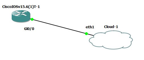
First i want to do just a connection as simple as possible, like this
I use GNS3 2.1.11 server on a VMWARE ESXi (5.5) and a laptop W7 (64) as client
My physical server VMWARE is connected to 4 ports trunk (making a network team) in a physical L2 2960 (about ten other VMs works in this server ESXi)
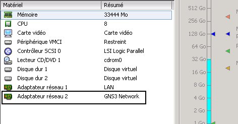
On my VM GNS3, i add a NIC, that is eth1 for the GNS3 cloud (eth0 is for the LAN making GNS3 working fine)
GNS3 network is tagged VLAN ID = 222 on the vSWITCH0
So I tried to collect the traffic from the cloud eth1 from an access port of my physical 2960 (mode access, and switchport access vlan 222), say port g0/5, and connect g0/5 to a port of one of my physical SW 3750, say g2/0/3, to test IP connectivity
From g0/5 (of the 2960) to g2/0/3 (3750) frames are not tagged, so the frame is vlan 1 inside 3750 (i hope i am right !)
So i put the router GNS3 g0/0 and int vlan 1 in my SW 3750 on the same subnet; but i cant ping between these interfaces.
Do i miss something ?
I will really appreciate a help
Regards
Hello Dominique
There are several ways to connect real equipment to a virtual GNS3 network. I’m not sure I can troubleshoot your particular setup, but Rene has a very good example in his GNS3 Vault site at the following link:
Some additional resources that may be helpful include some discussions on the GNS3 site on this topic.
I hope this has been helpful!
Laz
Hi, there.
The section 5 calculation is not entirely correct. There are brackets missing in the calculation.
Should be something like this:
Queue 2 will receive 20/70 = 0.28 * (100 Mbit – 5 Mbit) = 27.1 Mbit.
Queue 3 will receive 25/70 = 0.35 * (100 Mbit – 5 Mbit) = 33.9 Mbit.
Queue 4 will receive 25/70 = 0.35 * (100 Mbit – 5 Mbit) = 33.9 Mbit.
Thank you.
Hi,
I have two questions
-
My customer has a bunch of 2960s. I see in these 2960s, the qos is configured using mls qos, but the latest 9000 catalyst series using class-maps and policy-maps. What is the difference ?
-
When configuring priority queue on 2960s, I read in Cisco documentation, ‘the expedite queue is a priority queue, and it is serviced until empty before the other queues are serviced. You enable the expedite queue by using the priority-queue out interface configuration command.’ So if this is the case how do I enable policing to rate limit this queue to say 33% of the bandwidth ?
Thanks
Krish
Hello Adrtps
Catalyst 2960s, 3560s, and 3750s use what is known as Multilayer Switch QoS or MLS QoS. This has been replaced with what is known as IOS Modular QoS Command Line Interface (MQC) in platforms including the 9000, 3650/3850, and 4500E. This has to do with the way in which QoS is to be implemented on each type of platform.
The following Cisco live presentation is an excellent resource that shows, in detail, the way in which each type of syntax is to be applied.
https://www.ciscolive.com/c/dam/r/ciscolive/us/docs/2019/pdf/BRKCRS-2501.pdf
Here are some highlights of the presentation:
- Slide 22 - Describes the different types of software and syntax used for various platforms
- Slide 40 - Begins a section that describes in detail the configuration of MLS QoS (2960/3560/3750)
- Slide 58 - Begins a section that describes in detail the configuration of MQC (9000/3850/3650)
Concerning your second question, if Scheduled Round Robin (SRR) is enabled, only then will the expedite queue be serviced and emptied before all others. If you want to apply a specific policing value, you must apply that to the interface as a whole, as shown in the following lesson.
I hope this has been helpful!
Laz
1 Like
Thank you so much! These are good references
-Krish
1 Like
im not seing the video you mentioned in the website, can you please upload it to the page .
Hello Mehdi
Thanks for pointing that out. I will let Rene know to make the correction…
Laz
im new and learning, please don’t mind my questions
here is a topology : SW1,SW2 C1 CE1 PE1 P
Question 1) where the queue will be done
Question 2) let’s say the MPLS has a Qos without the queue and threshold thing configured, will configuring queue change things??
Question 3) can Qos be applied to VRF ?
Hello Mehdi
We don’t mind at all! That’s what the forum is for!
Where you apply queuing is not only dependent on the topology, but also on the expected traffic patterns, and the locations where you believe you will have congestion. Typically, queuing should be applied at the output interface of each device where congestion may occur. If a packet needs to be sent out and the outgoing interface is busy, the packet will be queued. Now if we’re talking about queuing on switches, like in this lesson, then you should apply it on all outgoing interfaces of switches within your topology.
So you’re saying that the MPLS network itself has some QoS mechanisms enabled correct? In your topology, only the PE1 and P devices are part of the MPLS core, so if QoS is being applied on MPLS, it would be applied on these devices. If you apply QoS on SW1 and SW2 this will not change the QoS policies on the MPLS network, but it will affect the traffic patterns you see, but only on the switches themselves.
The queuing described in this lesson using the mls qos commands, is a Layer 2 QoS mechanism. VRFs are Layer 3 entities. So if you’re asking specifically about the queues as they are applied in this lesson, these would be applied independently of any VRFs. However, it is possible to apply QoS to specific VRFs, but only those QoS mechanisms that operate on Layer 3. That includes things like shaping and policing.
I hope this has been helpful!
Laz