Hi,
ip route 2.2.2.0 255.255.255.0 192.168.12.2
Why there is no reverse route from branch ?
Thanks
Hello sims.
In order to answer your question, it is important to understand the difference between a remote route and a directly connected route.
From the perspective of the HQ router, the 2.2.2.0 network is a remote route. If no static route is configured or if no routing protocol is configured on the HQ router, there is no way for HQ to “know” about this network. This is why a static route was configured in the example.
From the perspective of the Branch router, both the 2.2.2.0 AND the 192.168.12.0 networks are directly connected, so the Branch router knows how to reach hosts on both networks. Since we are pinging 2.2.2.2 which is the Fa 1/0 interface of the Branch router, no reverse route is necessary because the Branch router already knows how to reach 192.168.12.1 which is the IP of the host who initiated the ping.
I hope this has been helpful!
Laz
19 posts were merged into an existing topic: How to configure static route on Cisco IOS Router
Hi Rene,
I got a bit stuck in my static routing lab, now im doing a static route between 3x Cisco routers, they are connected to each other via serial links, I have added all connected networks to all 3 routers but it seems that I can’t ping the interfaces of the edge routers (when I do show ip route x.x.x.x the network is there) so im wondering in static route, do we need to have some other configurations (other than adding static routes) to make all interfaces pingable( they all are up and with a valid IP address)
Thanks
Hello Said
As long as you have connectivity between directly connected routers and you’ve installed the remote networks on each router, you should be OK. No additional configuration should be necessary.
However, keep in mind that if your three routers are connected to each other in a loop, and you have created static routes to all possible networks, you may have created a routing loop.
I suggest you try to simplify your topology further and try configuring two routers only and have them share their networks. Once you get that working, you can expand to three and further configure routing to see where the problem occurs.
Keep us posted with your progress!
I hope this was helpful.
Laz
Hello Lazaros,
Thank you for your valuable reply.
My lab setup is as follows, I got R1 connected to R2 (in middle) and R2 is connected to R3, no connection is made between R1 and 3 (no loops here) now lets say R1 has networks 10.0.0.0 on fa interface and 192.168.12.0 on S0 —>R2
R2 has 2 networks 192.168.12.0 and 192.168.23.0 which connects to both R1 and R3
R3 has similar setup as R1, network 172.16.0.0 on its Fa interface and 192.168.23.0 on S0 -->R2
R2 have both directly connected networks plus 172.16.0.0 and 10.0.0.0 configured as static routes.
R1 has a static route to reach R3 via R2 and the same for R3
Interestingly, from R2, I can ping both Fa interfaces on R1 and R3, but can’t ping R3 Fa from R1 and vice verse, it just work fine if I configure a dynamic routing protocol, a bit weird to be as its a very simple concept but It just doest work ![]()
Appreciate your help here
Thanks a lot
1 Like
Got it working! my bad, just added a default route on both edge routers and it worked
Thanks for the help guys.
Sid
1 Like
Good day,
I understand what the default route of 0.0.0.0/24 does…it says push all networks (outside the routing table) to the next hop router. I don’t understand when to use this or why we would want to use this. Anyway to break down this idea a bit more for me ? Thank you in advance!
Regards,
Kevin
Hello Kevin
When a router makes routing decisions, it looks at the destination IP address in the packet and compares it with all of the routes in the routing table looking for a match. Specifically, it looks to see if the IP address is contained within the subnets in the routing table. So for example, if you have a routing table like this:
192.168.8.0/24 route to next hop IP 10.10.10.1
172.16.55.0/24 route to next hop IP 10.10.20.1
172.16.58.128/25 route to next hop IP 10.10.20.1
0.0.0.0/0 route to next hop IP 10.10.30.1
Let’s say a packet comes in to the router with a destination IP of 172.16.58.144. It will look through the routing table to see if there is a route to a subnet within which this destination IP address exists. Now the subnets expressed in the routing table essentially define ranges of IP addresses. Specifically, the 172.16.58.128/25 subnet has a range of IP addresses from 172.16.58.128 to 172.16.58.255 (including network and broadcast addresses). The destination IP address falls into this range, so the next hop IP that is used is 10.10.20.1 as indicated in the routing table.
Now if a packet comes into the router with a destination IP address of 192.168.1.50 for example, you can easily see that this is not in the ranges of IP addresses defined by the first three subnets which are:
192.168.8.0 to 192.168.8.255
172.16.55.0 to 172.16.55.255
172.16.58.128 to 172.16.58.255
However, the 0.0.0.0/0 subnet also defines a range of IP addresses. This range is 0.0.0.0 to 255.255.255.255, in other words, all of them! Why? Because a subnet mask of 0.0.0.0 or a designation of /0 essentially says that the whole address is a host portion of the network. Therefore this is a subnet that contains all possible IP addresses.
Naturally, if the destination IP address doesn’t match any of the first three subnets or IP address ranges, it will definitely match the 0.0.0.0/0 range. This is like a catch-all last resort bucket that matches everything that is not matched by a more specific routing table entry. So this is why this is the default route.
Now in your post you indicated 0.0.0.0/24. This actually defines an IP address subnet with a range from 0.0.0.0 to 0.0.0.255. I believe you meant to write 0.0.0.0/0 which is indeed the definition of a default route. Is that right?
I hope this has been helpful!
Laz
Hi,
is there an issue configuring two default route like below
ip route 0.0.0.0 0.0.0.0 1.2.3.1
ip route 0.0.0.0 0.0.0.0 1.2.3.2
Thanks
Hello Sims
No there is no issue. You can configure two default routes on a router, the router will simply do equal cost load balancing since both routes have an equal cost of 1 (static routes). Just keep in mind that packets routed to the default route will be distributed evenly across both links.
I hope this has been helpful!
Laz
Hello
If I want to avoid the possibility of recursive row what is the best solution? Use “ip route” command to specify a next hop IP address only or both the next hop IP address and a connected interface.
Thanks
If you want to disable recursivity to shorter prefix using different interface for next hop, simply configure static route with connected interface and next-hop ip address. Which means that static route is staying in RIB only if you can get to its next-hop using specified interface.
ip route 192.168.1.32 255.255.255.224 gigabitethernet0/1 172.16.1.1
When you configure only next-hop, you are allowing recursivity to shorter prefix that can use whatever interface as next-hop (because you are not specifying it).
ip route 192.168.1.32 255.255.255.224 172.16.1.1
In case you want to completly ignore recursivity you can use tracking object and bind this object to static route. But definitelly specifying interface and next-hop in static route is better solution.
Specifying interface in static route may be important, because static route is staying in RIB all the time next-hop is in range of any other route in RIB.
2 Likes
Hello Michal,
Thank a lot for clear explanation!
Hi Laz,
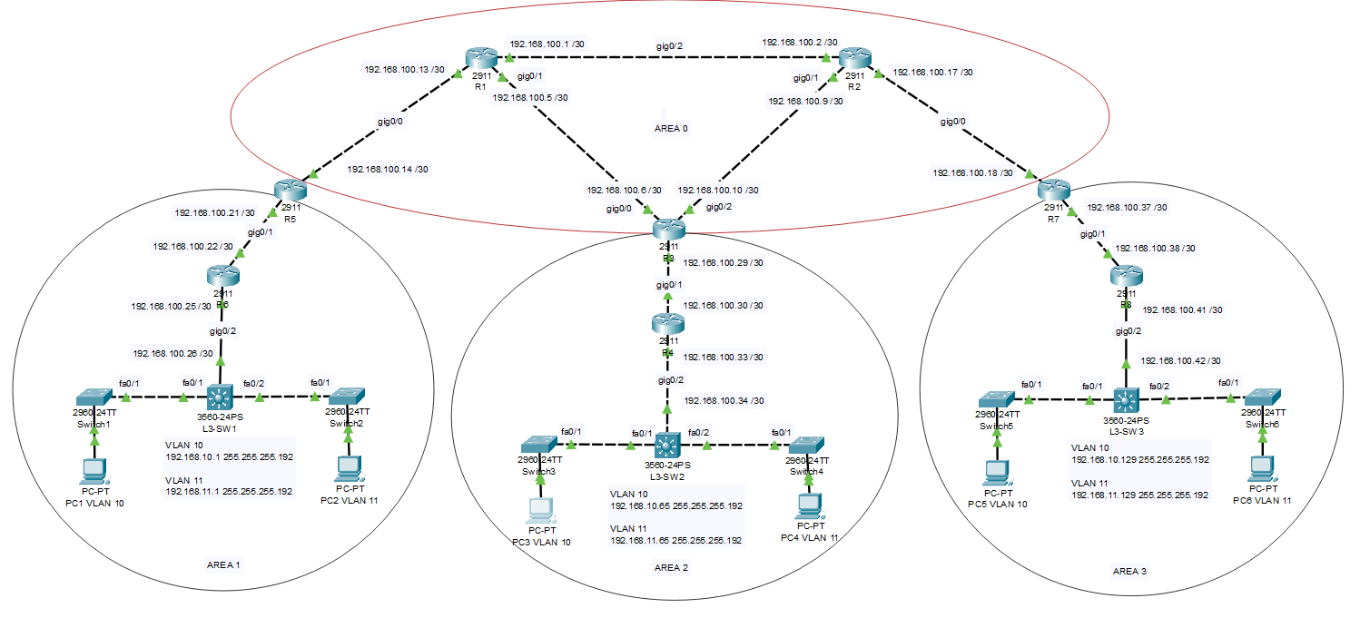
I manually assigned the IP address to PC 3 in VLAN 10
192.168.10.66 255.255.255.192, with a gateway of 192.168.10.65
Can you say if the configuration below is correct:
AREA 1 CONFIG
L3_SW1
int gig0/2
description TO R6
no switchport
ip address 192.168.100.26 255.255.255.252

int vlan 10
ip address 192.168.10.1 255.255.255.192


router ospf 1
network 192.168.100.26 0.0.0.0 area 1
network 192.168.10.0 0.0.0.63 area 1
AREA 2 CONFIG
L3-SW2
int gig0/2
description TO R4
no switchport
ip address 192.168.100.34 255.255.255.252

int vlan 10
ip address 192.168.10.65 255.255.255.192

router ospf 1
network 192.168.100.34 0.0.0.0 area 2
network 192.168.10.64 .0.0.63 area 2
PC 1 connected to L3-SW1 in Area 1 can ping to all the interfaces on all the routers.
When I use this command on L3-SW2 : network 192.168.10.0 0.0.0.255 area 2 , the hosts in Area 2 can ping to all.
When I use this command: network 192.168.10.64 0.0.0.63 area 2
PC 3 connected to L3-SW2 in Area 2 can ping to both interfaces on Router 4, and can
also ping to the interface on Router 3 connecting to Router 4, but PC 3 cannot
ping to the other interface on Router 3 connecting to router 1.
Also router 4 in Area 2 can ping PC1 in Area 1
I am not sure what is miconfigured or what is not configured, or how to troubleshoot this.
It seems like something has to be fixed on router 3
R3
int gig0/0
ip address 192.168.100.6 255.255.255.252
no shut
exit

int gig0/1
ip address 192.168.100.29 255.255.255.252
no shut
exit

int gig0/2
ip address 192.168.100.10 255.255.255.252
no shut
exit

router ospf 1
network 192.168.100.6 0.0.0.0 area 0
network 192.168.100.10 0.0.0.0 area 0
network 192.168.100.29 0.0.0.0 area 2

auto-cost reference-bandwidth 1000
R4
int gig0/1
ip address 192.168.100.30 255.255.255.252
no shut
exit

int gig0/2
ip address 192.168.100.23 255.255.255.252
no shut
exit

router ospf 1
network 192.168.100.30 0.0.0.0 area 2
network 192.168.100.33 0.0.0.0 area 2

auto-cost reference-bandwidth 1000
Hello Dinesh
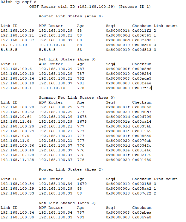
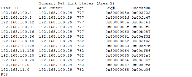
I see a couple of things that are problematic, and I’m not sure why they are there, but I hope that this will help you in your troubleshooting procedures.
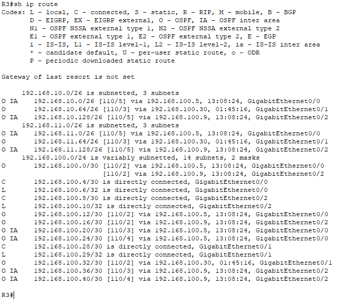
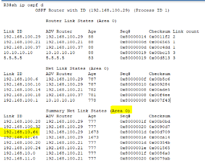
First of all, in the OSPF database in R3, I see the 192.168.10.64/26 network advertised in Area 0 where this should exist in Area 2:
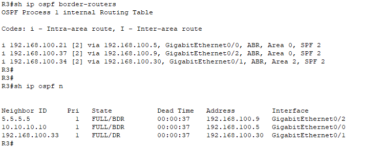
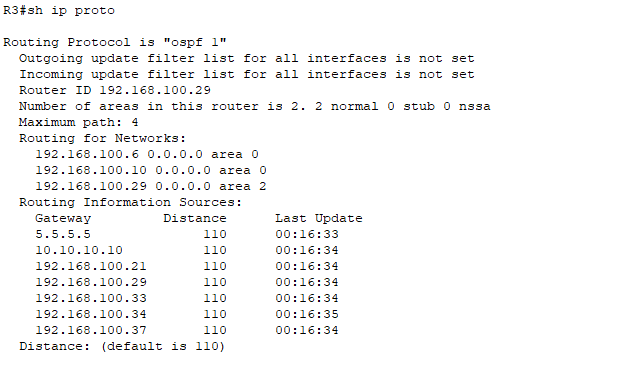
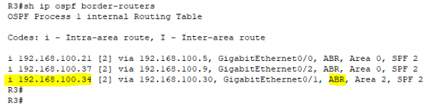
Secondly, I see that R3 believes that the L3-SW2 devices is an ABR which means that you have area 0 configured in its OSPF configuration as well:
Take a look at these and see if this helps you out in your troubleshooting…
I hope this has been helpful!
Laz
Hello Rene,
Static routes AD value is 1 by default.
But If we configure static route as below,
ip route 11.11.11.0 255.255.255.0 fa0/1
Instead of next hop ip address we are giving exit interface then what will be the AD value and why?
Hello Swapnil
A directly connected route will have an AD of 0
A static route that has a next hop IP will have an AD of 1
A static route that has an exit interface will have an AD of 0
This is the case because if you configure an exit interface, it is assumed that the destination network is on the network segment connected to the interface. In other words, it is considered a directly connected network.
I hope this has been helpful!
Laz
Hi Rene,
I’ve got a requirement at work in regards to configuring a static route in a certain way, I hope you can shed some light.
We have a collapsed core design with the Core switch at the centre of the design. All other modules (Internet-edge module, Server-farm module, etc.) are connecting off of this Core switch.
The company I work for is very security-oriented and for security reasons they have not added a default route on this core switch. They have a proxy server and all web-based traffic is sent to the Proxy Server IP address, which is included on the Core switch as a static route pointing to the IP of the Proxy Server, and then routes out to the Internet.
However, the business has a requirement to make a FIX connection to one of the trading platforms via the Internet. However, this particular trading platform want us to route to their platform via a public FQDN instead of IP addresses because the IP address assigned to this FQDN is dynamic and will change without warning (not sure why they’ve got it configured like that). They said they don’t even have a range they can provide so I can include the entire subnet(s) in static routes.
So I need to add a static route with the FQDN as the destination network instead of specifying the network address. Is there anyway to do this? I’ve searched online but could not find anything. The only thing that I could find that was close to what I’m trying to achieve is something called a FQDN ACL (passthru-domain-list). Below is the link to the Cisco article.
Passthru-domain-list
I also found the following article about specifying the FQDN in an extended ACL, referencing that in a route-map setting the next hop ip and then applying it under the client facing SVI on the core switch with PBR.
I’m confused and I’m struggling to come up with a solution.
Would really appreciate your advise and learn from your experience.
Many Thanks
Akhas
Hello Akhas
One way you could do this is to determine of the FIX API uses a particular port. If this is the case, then you could use policy based routing so that anything that uses that particular TCP port will be routed to the appropriate IP address. Something like this:
access-list 150 permit tcp any any eq 5555

route-map FIXtraffic permit 10
  match ip address 150
  set ip next-hop <next-hop-address-bypass-proxy>

interface vlan 200
  description Internet Facing Interface
  ip policy FIXtraffic
But this will only work if your TCP port for your FIX API is unique, otherwise non FIX traffic with the same destination port will also bypass the proxy server.
Alternatively, you can use an EEM script that you can schedule to run every few seconds to check what IP address the FQDN resolves to and use that in the access list used for your policy based routing. Whenever it changes, the access list will be changed, and routing will be maintained. You can find out more about EEM scripts and an example of their implementation at the following lessons:
Cisco IOS Embedded Event Manager
I hope this has been helpful!
Laz