Hello, I would like to know , if the examples are done in packet tracer and then you use wireshark?
Hello Ivonne
Most of Rene’s labs on the site are performed using Cisco Modeling Labs (CML) or Cisco Virtual Internet Routing Lab (VIRL), which is CML’s predecessor. Wireshark is used in conjunction with these emulators. In some rarer cases, where an emulator cannot fulfill the requirements of a lab, he may use real equipment, but not too often.
Cisco’s Packet Tracer is incompatible with Wireshark, so you cannot capture packets from a topology that you have created in Packet Tracer. However, Packet Tracer itself does have a utility to capture and display the content of packets as they go through the network.
I hope this has been helpful!
Laz
Hello, everyone!
Regarding security. I’ve read that ICMP pings can be used as an attack tool such as ICMP Flood where the attacker attempts to quickly generate as many pings as possible in an attempt to overwhelm the destination device. However, Google also says that for this reason, ICMP should be disabled.
But how are we supposed to verify basic connectivity in cases like troubleshooting if we disable pings or configure our devices not to respond to them?
Thank you.
David
Hello David
Indeed, ICMP can be leveraged for various attacks including ping flood, ping of death, ICMP smurf attacks, ICMP redirect attacks, and various others. Most of these are DoS attacks. In any case, they all exploit ICMP’s fundamental mechanisms and features for malicious purposes.
There are various ways to deal with these, but arguably the most effective (and simplest to employ) is to disable responses to ICMP completely. You will often see this approach on routers that are found on the Internet. If you have done a traceroute to a destination on the Internet, you will see that some hops along the way don’t respond. This is because they have been configured not to respond to ICMP messages for security reasons.
Now this solution is not always preferable for the reasons you stated in your post. Ping and traceroute are valuable utilities for troubleshooting networks. So there are two primary approaches:
- If you choose to disable ICMP completely, then you must use other methods to troubleshoot. This can include using tools like:
- traceroute with TCP or UDP - On Linux for example, the
traceroutecommand by default uses UDP, not ICMP. You can usetraceroute -Twhich will conduct a “traceroute-like procedure” using TCP instead.
*TCP and UDP port scans can also be used to determine if devices are active and listening to those particular ports - On a local network, you can use ARP to find the MAC address associated with a particular IP address, and thus you can also identify which devices are currently active on the local network.
- Monitoring tools - Using SNMP, Netflow, or other network monitoring tools and protocols, you can determine device connectivity without using ICMP.
- Other options include using DNS queries, SSH, Telnet, and application-level health checks.
- traceroute with TCP or UDP - On Linux for example, the
- The other approach is to not disable ICMP but to implement strategies that will help mitigate the risks associated with ICMP while still maintaining its benefits. THis approach can include:
- Selectively filtering ICMP traffic based on ICMP message types and geographical blocking of particular IP addresses
- Rate limiting ICMP packets to avoid DoS attacks
- Actively monitor ICMP traffic on the network to preemptively deal with attacks
There is no single best solution for all cases, it should be examined on a case by case basis. Disabling ICMP completely is easiest, but if you need ping and traceroute for troubleshooting (as well as for other possible features) then the alternative is to mitigate any such attacks as described above.
I hope this has been helpful!
Laz
why ARP is a layer 2 protocol?
I think of it a bridge between layer 2 and 3. However, since ARP contains IP addresses
in the header, I would call it a layer 3 protocol (Sender IP address, Sender MAC address, etc.) are some of the fields in the header. Am I correct?
Hello Faisal
ARP does indeed contain IP addresses in the header, but not for the purpose of routing the ARP messages to their destinations. The IP addresses contained in the ARP messages are used to determine the MAC address of the intended destination. They don’t play a role in getting the message to where it needs to go. Thus, it is a Layer 2 protocol. Does that make sense?
I hope this has been helpful!
Laz
Thanks for your reply.
I would say that you probably have way more experience in the field of networking than I do. However, please allow me to disagree. I have some points to make regarding this topic, and I know it is a bit contraventional.
1- The OSI model (or the TCP/IP) are frameworks to help us understand, design, and troubleshoot networks. They are not a prefect reflection of the world. These models try to fit everything into neat boxes, life doesn’t work that way. It is hard to fit everything into neat boxes, ARP is a great example of that.
2- I see lots of experienced network engineers disagree on this subject, some would say it is a layer 2 protocol, others would argue that it is a layer 3 protocol, and some would even tell you that it is a layer 2.5 protocol! My take is that it’s a bridge between layer 2 and 3. So, I would consider it a layer 3 protocol or a layer 2.5 protocol. If that makes sense. Also, ARP is indeed (at least in my opinion) participate in getting the message to its final destination. Consider the scenario where a host needs to communicate with another host on a remote network, it will need to forward the message to its default gateway. Thus, using ARP in the process to discover the MAC address of its default gateway which is considered the first hop in the path to the destination. I know ARP doesn’t “transport” the message, but it is an important piece of the puzzle to get the message to the very first hop.
This discussion is quite informative. Excuse me for any inconvenience.
Thanks.
Hello Faisal.
The concept behind ARP being L2 or L2.5 is a rather… contentious topic amongst many communities ![]()
There are several arguments for and against.
For example, you already know what the IP address of your destination is. You then use ARP to learn the MAC address associated with that host/next hop for mapping purposes which is all L2.
But then again, you use layer 2 to provide layer 3 info. You can use it to confirm layer 3 configuration/information.
Oh but wait, ARP doesn’t actually use an IP header. Here is how it looks like in Wireshark
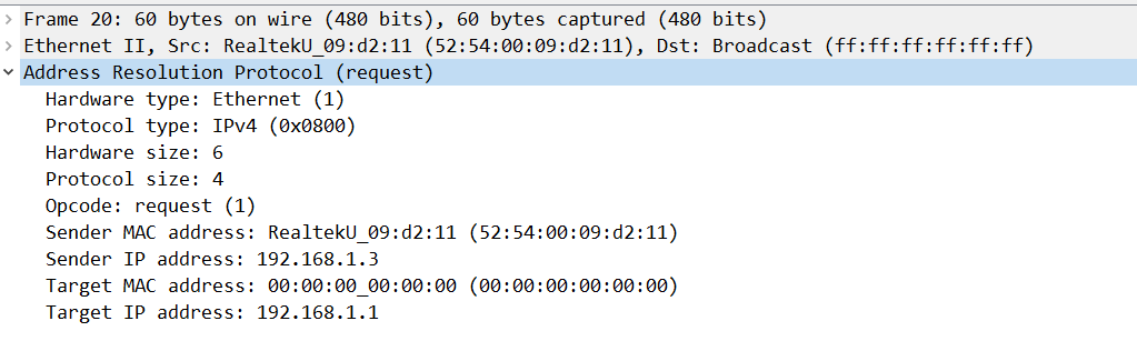
But then again, you can argue that ARP is the go-between IP and Ethernet and that it exists between these two protocols.
It’s a rather complicated topic to discuss and I don’t think that there is a clear definitive answer to this problem. My take on it is that it’s a layer 2 protocol. There is no IP Header and you already know the IP address, you just need the MAC address. As you’ve seen from the Wireshark capture, ARP lies on L2.
Whichever angle you take on it, there will be people who will agree and people who will disagree, atleast that’s how I view it. I wouldn’t bother too much with differentiating between whether it’s actually L2 or maybe L2.5. As long as you understand the protocol and what it does, you’re good for the exam and for the real world.
And good question, by the way! It’s always fun to have such discussions. It shows that you’re thinking about the protocol and not just accepting whatever your study resource mentions.
David
1 Like
Great post!
I agree with your conclusion.
Thanks for replying!
1 Like
Hello Faisal
Thank you for sharing this thought process, it’s always beneficial to express our views and share our ideas. It doesn’t matter how much experience we each have, reexamining and thinking about these concepts is always beneficial. Discussion is part of what helps us to learn, so thanks for engaging!
Here is my take on the topics that you touched upon:
Concerning the OSI and the TCP/IP models. These, indeed, are frameworks that help us understand, design, and troubleshoot networks. However, these models are not just ways for us to understand networking operations, but all protocols that fall within this framework are designed to conform to these models. So, by definition, network protocols conform to these models so they can operate and interoperate with other protocols.
Are there exceptions? Yes there. For example, tunneling repeats certain headers to achieve its goals. MPLS is an example of a “layer 2.5” protocol, and violations of the “layer boundary” can take place with application layer operations interacting with lower layer mechanisms such as is the case with TLS security. However, even such violations are very specifically documented and they still conform to specific rules.
When we examine a specific protocol, it must be examined within the scope of its operation. Yes, ARP does aid in allowing a host to communicate with another host in another subnet, thus Layer 3 is involved. But strictly speaking, the operation of ARP only exists within a single subnet. With the exception of Proxy ARP (another exception to the operation of the layered models), ARP packets cannot exit the broadcast domain they were generated in. Indeed, they cannot be routed, because their headers don’t contain any information concerning Layer 3 addressing (for routing). As such, within the scope of the operation of ARP, if the packet can’t be routed, it, by definition, is not Layer 3, but is confined to Layer 2.
ARP is indeed an important part of the puzzle to get the message to the very first hop, but that in itself does not make it a Layer 3 protocol. Its operation is discrete and distinct from other operations, thus looking at only the scope of the operation of ARP, I would have to say that it remains within Layer 2.
I hope this has been helpful!
Laz
Hello, everyone.
When it comes to ICMP, there are several components/utilities such as ping that can be used for network diagnosis. For example, a simple ping consists of an ICMP Echo Request message that is sent to the destination and an ICMP Echo Reply that is sent to respond to the requests to verify basic connectivity .
How is it with traceroute, though? Traceroute isn’t on its own an ICMP message but it does rely on the ICMP TTL Exceeded message in order to perform its operation, correct?
So how is it with traceroute? Is traceroute a part of ICMP/is it an ICMP component or is it separate from it?
And when it comes to unreachable messages, what exactly is the difference between these two?

Cisco IOS always replies with “1” if there is no route while a CheckPoint FW replies with 0, so I suppose that this is vendor-based. Does Cisco IOS ever use 0, though?
Thank you.
David
Hello David
Ping is a utility that uses ICMP, and it is generally uniformly deployed across all types of devices, platforms, and operating systems. So, a ping from a Windows PC will work almost identically to a ping from a Cisco switch.
Traceroute however, is highly platform-specific.
- In Unix/Linux systems, traceroute by default sends a sequence of UDP packets with destination port numbers ranging from 33434 to 33534, so ICMP is not involved at all! But you can modify the command to use ICMP instead, or even TCP if you like.
- On a Windows device, traceroute (or tracert as the command is named) uses ICMP echo request packets by default.
- Cisco’s implementation also uses UDP datagrams with incrementing TTL values.
So you’ll have to see which platform the command is issued on and what keywords/switches/options are used to understand the behavior.
As for ICMP codes, the difference between 0 and 1 is the following.
If you send an ICMP packet to a destination of 192.168.12.5, and somewhere along the path, a router has no entry in its routing table for this specific network, the packet is dropped and an error code of 0 is returned. The destination network is unreachable.
However, if the ICMP packet reaches a router that has the 192.168.12.0/24 network directly connected to one of its interfaces, then the destination network IS reachable. So the router attempts to send the packet to the 192.168.12.5 host. If no host responds, then the router will send an error code of 1, saying the host is unreachable.
In the first case, the destination network is unreachable. In the second case, the destination network is reachable, but the specific host in that network is not. Does that make sense?
Now what each vendor will use may vary, but as far as I know, the ICMP codes should be consistent across all vendors. Are you sure that the Cisco device and the CheckPoint device ICMP code results were not due to the fact that the situation was indeed different in each case? Take a look and let us know…
I hope this has been helpful!
Laz
Hi andrew
Could you plz explain if we traceroute wrong destination then how many hops source RTR would follow TTL value or is it possible for destination RTR to do same thing if we have multiple requests of correct destinations are getting from another correct sources or applications?
Hello Kanu
If I understand correctly, you want to find out how traceroute behaves if you traceroute a wrong nonexistent destination, correct?
So if you have something like this, how is the TTL handled?
C:\> tracert 192.0.2.1

Tracing route to 192.0.2.1 over a maximum of 30 hops

  1     2 ms     1 ms     1 ms  192.168.1.1
  2    10 ms     9 ms     8 ms  203.0.113.1
  3    15 ms    14 ms    13 ms  203.0.113.5
  4    22 ms    21 ms    20 ms  198.51.100.9
  5    35 ms    34 ms    33 ms  198.51.100.13
  6     *        *        *     Request timed out.
  7     *        *        *     Request timed out.
  8     *        *        *     Request timed out.
  9     *        *        *     Request timed out.
 10     *        *        *     Request timed out.
 11     *        *        *     Request timed out.
 12     *        *        *     Request timed out.
 13     *        *        *     Request timed out.
 14     *        *        *     Request timed out.
 15     *        *        *     Request timed out.
 16     *        *        *     Request timed out.
 17     *        *        *     Request timed out.
 18     *        *        *     Request timed out.
 19     *        *        *     Request timed out.
 20     *        *        *     Request timed out.
 21     *        *        *     Request timed out.
 22     *        *        *     Request timed out.
 23     *        *        *     Request timed out.
 24     *        *        *     Request timed out.
 25     *        *        *     Request timed out.
 26     *        *        *     Request timed out.
 27     *        *        *     Request timed out.
 28     *        *        *     Request timed out.
 29     *        *        *     Request timed out.
 30     *        *        *     Request timed out.

Trace complete.
So for each additional failed probe, is the TTL increased? Yes it is. This is because you may have routers along the path that are configured to relay traceroute probes, but not to respond to them. So if you have this topology:
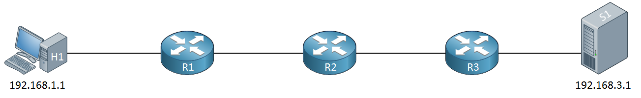
…and R2 is configured not to respond to traceroute probes, but it will forward them to the next hop, you could have this:
C:\Users\vmware>tracert 192.168.3.1

Tracing route to 192.168.3.1 over a maximum of 30 hops

  1     1 ms     1 ms    <1 ms  192.168.1.254
  2     *        *        *     Request timed out.
  3     1 ms     1 ms     1 ms  192.168.23.3
  4     1 ms    <1 ms    <1 ms  192.168.3.1

Trace complete.
So even though probe 2 failed, you would want probe 3 to increase the TTL so the probe can be relayed to R3. Otherwise, if it does not, it will continue to fail.
Is it possible some other routers in the path or the destination router itself will do something to try to correct such behavior? Well, no, the routers in the path that respond correctly won’t affect how the wrong traceroute behaves. The routing process is independent of how traceroute works, and this is a good thing, because traceroute is used to detect possible failures. If traceroute corrects for those routing failures, then you don’t have a proper diagnostic of the situation of the network… Does that make sense?
I hope this has been helpful!
Laz
But it is mentioned ipv4 packet header lesson TTL is decremented? Please confirm what is correct statement?
Time to Live: Everytime an IP packet passes through a router, the time to live field is decremented by 1. Once it hits 0 the router will drop the packet and sends an ICMP time exceeded message to the sender. The time to live field has 8 bits and is used to prevent packets from looping around forever (if you have a routing loop).
Hello Kanu
Ah I see the confusion. Indeed, every time a traceroute probe is sent, it has a TTL in the IP header. As the packet goes from router to router, the TTL value in the header is decremented by 1 until it reaches 0, then it is dropped.
However, with traceroute, the next probe that is sent, is sent with a TTL that is 1 higher than the previous probe. That way, that probe will be able to reach the very next hop in the route to the destination.
So when a probe is sent out, it has an initial TTL value, and as it goes from router to router, that TTL is decremented.
The next probe wil have an initial value that is incremented from the previous probe, and it till will have that value decrimented as it goes from router to router.
Does that make sense?
I hope this has been helpful!
Laz
Hi @ReneMolenaar,
I read in the documentation that the TTL field will decrease every time it passes through a hop. But in the documentation it says “increase”. This contradicts the theory, can you clarify this part?
“Cisco IOS uses UDP packets with a TTL value of 1 and destination port 33434. The TTL and destination port will increase for every hop”
Hello VO LE HUY
When we talk about traceroute, there are a couple of things we need to keep in mind. Traceroute sends out multiple probes. Each probe that is sent out will indeed have its TTL decreased at each hop until it reaches 0 where it is dropped.
However, each subsequent probe that is sent out will have:
- the initial TTL incremented
- the UDP port being used incremented.
Take a look at this traceroute on a Cisco IOS device:
Router# traceroute 172.16.8.23

Type escape sequence to abort.
Tracing the route to 8.8.8.8

  1  192.168.1.1  2 msec  1 msec  1 msec
  2  10.10.10.1  4 msec  3 msec  4 msec
  3  172.16.5.2  9 msec  8 msec  9 msec
  4  172.16.8.23  15 msec  14 msec  15 msec
The above has four probes. When the first is sent it, its TTL is 1 and its UDP port is 33434. The TTL is decremented as it goes through the topology. However, the second probe has a TTL of 2 and a UDP port of 33435. Again, as it goes through the topology, the TTL is decremented at each hop. The third probe has an initial TTL of 3 and a UDP port of 33436, and similarly the fourth probe has a TTL of 4 and a UDP port of 33437.
So the initial TTL and UDP port are incremented for each subsequent probe, but the TTL is indeed decremented on each hop. Does that make sense?
I hope this has been helpful!
Laz
1 Like
Thank @lagapidis !!! I think the explanation in the documentation should be tweaked a bit.
“… The TTL and destination port will increase for every probe”
1 Like