It includes the AFI and IDI in the area address. Does Cisco ignore or not recognize the first two? Or are they used so little that they decided to completely omit it?
A Cisco Live presentation says this:
IS-IS Addressing - Sample NET Addresses 8-byte Area ID / System ID
Area Address        Station ID        SEL
┌──────────┐        ┌──────────────┐  ┌──┐
07          .1921.6800.1001          .00
└──────────┘        └──────────────┘  └──┘
     Area
Area Address: 07
Station ID (System ID): 1921.6800.1001
SEL (NSEL): 00
10-byte Private AFI / Area ID / System ID
Area Address
┌──┬──────┐        ┌──────────────┐  ┌──┐
49 .1234   .1921.6800.1001          .00
└──┴──────┘        └──────────────┘  └──┘
 AFI  Area         Station ID        SEL
AFI: 49 (Private)
Area ID: 1234
Station ID (System ID): 1921.6800.1001
SEL (NSEL): 00
OSI NSAP Format
Area Address
┌──┬────┬──────┐   ┌──────────────┐  ┌──┐
49 .0456 .1234   .1921.6800.1001    .00
└──┴────┴──────┘   └──────────────┘  └──┘
 AFI Domain  Area       Station ID   SEL
AFI: 49
Domain (IDI): 0456
Area (HODSP): 1234
Station ID (System ID): 1921.6800.1001
SEL (NSEL): 00
Apparently, the Area Address consists of the AFI, IDI, and the Area number.. So the area address is not the same as the area or is it? I’ve tried changing the AFI or Domain while keeping the Area number the same and the routers formed only a L2 adjacency so I don’t think they considered the area to be the same
There are many acronyms used here and this can get confusing!! Let’s first see what the official authoritative addressing scheme is and then we’ll see how Cisco interprets it:
The HODSP is variable length between 0 and 96 bits (based on the constraints of the rest of the fields)
The system ID at 48 bits
the NSEL at 8 bits (which is always 0 for IS-IS use)
Note that:
The AFI + IDI is defined as the Inter-Domain Part or the IDP
And overall, the Area address is the AFI + IDI + HODSP
And the max size of the Area address is 13 bytes
However, because virtually all IS-IS deployments use an AFI of 49 (private addressing), the IDI is almost always zero length. Thus, the AFI is essentially the IDP in this case.
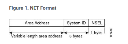
So the overall structure is this:
|    Area Address    |   System ID   |  NSEL |
|    IDP    | HODSP  |   System ID   |  NSEL |
|AFI  | IDI | HODSP  |   System ID   |  NSEL |
Now keep in mind that IS-IS didn’t invent these fields, they are part of the OSI Layer 3 addressing standard, and IS-IS simply uses them.
Now going on to Cisco. Indeed, Cisco does not mention the IDP or IDI or the AFI for that matter (I didn’t find it in the documentation you sent). I see it in the Cisco documentation you shared, where it does mention the AFI, but the rest of it calls it simply the “area,” where officially this is the HODSP.
Cisco simply doesn’t go into the details of the structure of the area address simply because it is not necessary for the purposes of IS-IS. This is a practical simplification, not a technical omission.
I hope this has been helpful!
Laz
PS I replaced your image with text that says the same thing for copyright purposes.
I never quite understood one thing. IS-IS is built with TLVs. If something needs to be added or removed, the designers can just add or remove the relevant TLV.
What I don’t quite understand is.. what makes these TLVs so flexible and extensible? Can’t OSPF, for example, also add extensions to itself without TLVs?
The “magic” of TLVs lies in how routers parse packets:
TLV stands for Type-Length-Value, and each of these has its role:
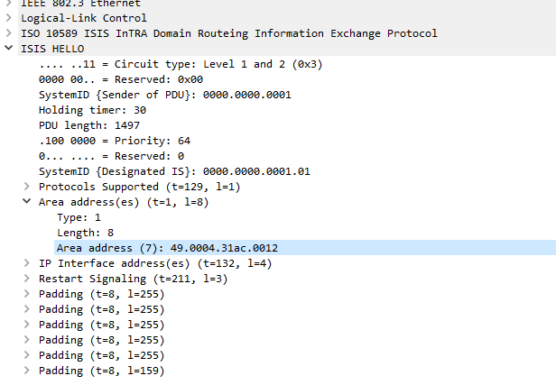
Type: Identifies what kind of information this is (e.g., Type 1 = Area Addresses, Type 22 = Extended IS Reachability)
Length: Specifies how many bytes of data follow
Value: The actual data
So when an IS-IS router encounters a TLV, it first reads the Type field. If this field is recognized, the contents of the Value field is processed according to specifications. If the Type field value is unrecognized, the Length field is used to skip exactly that many bytes and continue to the next TLV.
This allows routers that don’t understand particular TLVs to continue operating normally while safely ignoring whatever it doesn’t understand. This prevents the failure of the whole process. It also makes the modification of IS-IS much easier because there is a standardized way of extending its capabilities.
Now, can OSPF add extensions without TLVs? Sure it can, but not easily and not without needing to redefine the fundamental framework of the protocol. The rigidity of fixed LSAs forced OSPF to evolve. RFC5250 introduced Opaque LSAs (Types 9, 10, 11) which provide a generic container that carries… ahem… TLVs inside.
So both protocols CAN be extended today, but:
IS-IS: Extensibility is native and simple, just define a new TLV type
OSPF: Required retrofitting extension mechanisms (Opaque LSAs with embedded TLVs) because the original fixed-field approach was too rigid.

8-byte Area ID / System ID
10-byte Private AFI / Area ID / System ID
OSI NSAP Format