Hello Brahim
Beyond this lesson, there is no content on metro Ethernet or VPLS on the site. However, you can find information about these features at the following Cisco documentation:
I hope this has been helpful!
Laz
Hello Brahim
Beyond this lesson, there is no content on metro Ethernet or VPLS on the site. However, you can find information about these features at the following Cisco documentation:
I hope this has been helpful!
Laz
Hi Network gurus,
We used to have MPLS L3 VPN. NOW, changing the new provider, it is changed to VPLS, layer 2. To connect inter site, we need to adjust routes etc on VPLS.
For MPLS L3, the routes are established putting next hop as Provider IP but now, no IP nothing. My understanding is VPLS is completely Layer 2. Question is how to connect inter site ??
Hello Binod
Yes, you are correct VPLS is indeed a Layer 2 technology, so there is no routing involved. VPLS is a type of Metro Ethernet, which essentially delivers a Layer 2 pipe to each of your remote sites.
VPLS is one of several implementations of Metro Ethernet that you can find out about in this lesson:
VPLS is sometimes called Ethernet LAN service.
How do you implement routing in this scenario? You do so on your own devices, completely independent of the ISP. Imagine that the Layer 2 connections that terminate at your remote locations conceptually act as a single Layer 2 switch allowing your sites to communicate using Ethernet. If you have a router at each site, then those routers can communicate with each other over Layer 3 by placing them all in the same subnet, and configuring your routing accordingly.
I hope this has been helpful!
Laz
Hi Lagapides,
Thank you so much for your reply. Yes, understood that VPLS is totally transparent transport mechanism and independent of ISP routing and got through the articles in this topic, THANK YOU AGAIN.
Yes, I connected the CE to PE connecting port in each site. Established a NEW vlan with private IP of same subnet, eg. 192.168.10.0/24. I can ping each site. I have just untagged the switch port in each site which is connecting to PE router (ISP), not tagging any LOCAL VLANs. AND , I have adjusted the static route accordingly.
i.e. to reach SITE A to B, with CE port on VLAN, given the IP 192.168.10.1, 192.168.10.2
ip route <Destination_subnet> 192.168.10.2 , here 192.168.10.2 is the next hop, w hich is cool so far.
My questions,
1.
Is this the correct way of doing or should I tag local vlans in each site ? VLANs numbers are same in each site but subnets are different. For example, vlan 100 in SITE A, 10.100.0.0/24, site B, 172.27.0.0/24.
Sorry, to many questions but please kindly share your suggestion; I really need to get it done. Any information needed, please kindly ask.
Also, @ReneMolenaar , would appreciate your feedback on it. Do we need to use the dynamic routing protocol or static is fine here ?
Sincere thanks,
Binod
Hello Binod
Great to hear that it’s working well for you and you have communication between sites.
It really depends on your architecture. If each site is connected only via Layer 3 then you don’t have to share VLAN tags between sites. Since you have a different subent at each site, this works just fine. Now if you were to send multiple VLANs through the VPLS using QinQ then you would be spanning VLANs across the Metro Ethernet link. Generally speaking, this should not be done unless absolutely necessary. Spanning VLANs across sites can be inefficient especially for broadcast traffic.
How should the remote site connect to the Internet? Will all that traffic be routed over the VPLS to the main site and sent out from there? Or is there a local Internet connection? Based on your question, I assume it will be routed to the main site, and then go out to the Internet from there. If that is the case, then yes, you can create NAT translations for those subnets in order to allow them to reach the internet. Instead of creating multiple address pools for NAT translation, you can summarize them into a single command, if that works better for your specific IP addressing scheme, to incorporate all internal addresses.
Again, it depends upon your architecture. If the network is simple, and has relatively few routers, static is fine. Also, if you don’t have alternate routes that can be used in the event of a failure, static is fine. If however your network has several paths that traffic can take, and those paths need to be automatically used in the event of a failure, then dynamic routing is preferable.
I hope this has been helpful!
Laz
Hi Lagapides,
Thank you. Untagged the upstream port in same subnet for all sites, then used static routes, just four SITES. It is done, everything GOOD.
For example, for upstream port which is connected to VPLS trunk in each site, configured a vlan with IP same class. eg. 192.168.0.0/24, .1,.2 and .3. I could reach and used the static route as needed. funtastic..
Next question/discussion is about SPANNING-TREE. We do have root bridge in each remote sites.
SITE A: main site, bridge priority of core switch 0
SITE B: second site for example.: bridge priority of core switch 32768 and configured root.
Since we are saying, this is single BROADCAST Domain, is all topology handled by Core Switch Main Campus (priority 0) ? In our case, possibly NOT ?
What happens if we configure SITE B core switch with Priority 0 ?
Please share your view/thought.
-BINOD
Hello Binod
STP will function as if the metro Ethernet infrastructure is simply a switch. This “virtual switch” doesn’t participate in the STP process, however, so you can imagine that all edge switches at all sites will share their BPDUs directly with each other. STP will simply function and will elect the switch with the lowest priority value (thus the highest priority) as the root bridge.
So yes, the core switch at the main campus with a priority of 0 will become the root bridge. If you configure SITE B core switch with a priority of 0 as well, then it is the lowest MAC address that is used as a tiebreaker for the root bridge.
More info about STP, priorities, and root bridge elections can be found here:
I hope this has been helpful!
Laz
Hello Laz,
I was wondering, if this metro technologies is a L2 protocol, then why inside the isp network we don’t use Vlans to connect the customer’s dispersed sites,
I mean in design perspective when should we use VPLS or VPWS, xconnect,…etc, is that depend on the isp’s backbone network equipment’s?
Hello Ahmedlmad
Actually, we can use VLANs within the Metro Ethernet infrastructure of the ISP to interconnect multiple customer sites. It is natively part of Ethernet so there is no restriction to using it. However, there are some good reasons not to use VLANs that have primarily to do with scalability, reliability, and security. One issue, in particular, is that you can have only up to 4096 unique VLAN IDs based on the 12-bit VLAN ID field in the VLAN tag. Many ISPs will have more customers than the VLAN ID can provide.
Some technologies such as 802.1Q also known as QinQ, help to resolve this, by assigning a single ISP VLAN to a customer, and that customer can tunnel all of their own VLANs through that single ISP VLAN. However, even with QinQ, scalability is still an issue.
Typically VPLS, VPWS and connect are preferred over simple VLANs for Metro Ethernet. WHere each one will be used depends upon the ISPs backbone equipment but also on customer requirements and the desired level of service and security. Here is a brief description of how you would use each of these other technologies:
VPLS provides a point-to-multipoint Layer 2 VPN service delivering a virtualized Ethernet switching service across an IP/MPLS network. It is suitable for customers who require a seamless, transparent LAN service between multiple sites. VPLS is more scalable than VLANs and supports advanced features like QoS (Quality of Service).
VPWS is a point-to-point Layer 2 VPN service that emulates a virtual leased line or virtual private circuit between customer sites. It is suitable for customers who require a dedicated, point-to-point connection between two sites. VPWS is simpler to implement than VPLS but doesn’t provide the full Ethernet switching functionality.
Xconnect, which can be either L2TPv3 or MPLS based, is a point-to-point Layer 2 tunneling mechanism that can be used to transport customer traffic between two sites. It can be used with either L2TPv3 or MPLS as the underlying transport technology. Xconnect is a more basic service than VPLS or VPWS and may be suitable for customers who require a simple, point-to-point Layer 2 connectivity service.
I hope this has been helpful!
Laz
Hello Dear,
Thanks for your excellent reply, one more concern!
Could you explain what does transparent transport for the customer’s frame means when VPLS,VPWS are used and why simple vlan technology doesn’t provide that ?
BR
Ahmed
Hello Ahmedlmad
When we talk about transparent transport in this context, it refers to the ability of these services to carry customer frames between sites without any modification to the frame structure or content. The service provider’s network is essentially invisible to the customer’s network, making it appear as though their sites are connected through a single, large Ethernet LAN.
Technologies such as VPLS, VPWS, as well as 802.1q or “QinQ” all deliver this transparent transport.
So the question is, why is simple VLAN technology not considered to have the same level of transparent transport? Well, simply put, simple VLANs are not really a tunneling technology.
VLANs segment a single physical LAN into multiple virtual LANs. Using the VLAN tag, we can determine on which VLAN a particular frame exists. However, beyond the tag, there are no other features that can be used to encapsulate and tunnel traffic transparently across an ISP network.
VPLS and VPWS, for example, can encapsulate customer frames with either MPLS labels (or L2TPv3 headers in the case of L2TP-based VPWS) as they enter the service provider’s network, isolating customer traffic and delivering a high level of transport transparency.
These along with additional features such as pseudowire emulation, virtualized Ethernet switching, and others, make VPLS and VPWS well-suited for transparently tunneling traffic between customer sites over an ISP’s network.
I hope this has been helpful!
Laz
Hello, everyone.
I have a few questions.
Thank you
David
Hello David
These questions really help clarify what Metro Ethernet is and how it works.
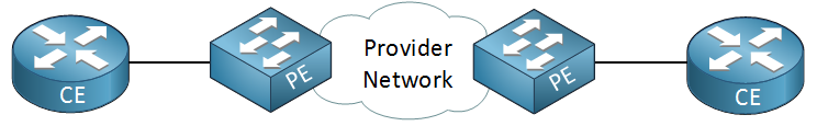
From the customer’s perspective, there is no “metro-Ethernet-specific” configuration on the customer equipment. The customer typically sees a standard Layer 2 Ethernet port being offered from the provider.
It connects to the telco equipment that is brought to the customer’s site. A Metro Ethernet service that one of my clients works with uses Cisco 3560 compact switches as the telco equipment. Others may simply bring you a fiber cable whose other end connects to a switch at their own Point of Presence (POP). But ultimately, it is just an Ethernet port that is provided for the customer.
Actually, they do just have a switch there. But what happens inside the ISP can be quite intricate. There are several options depending on the underlying infrastructure:
The benefits of Metro Ethernet are that the customers simply get a Layer 2 port on their infrastructure. The whole Metro Ethernet infrastructure, from the point of view of the customer, is one big L2 switch. This greatly simplifies the implementation of the customer sites.
I hope this has been helpful!
Laz
Hello Laz.
Sorry for the late reply and thank you so much. I have one more question. What device exactly connects to the provider’s network? Does the customer use a switch or a router, or can both be used?
In this case, if we use routers, the L2 connectivity would surely be extended but only between the CEs since routers break down broadcast domains, or not? So anyone behind the CEs wouldn’t have extended L2 connectivity, if what I am saying makes sense.
David
Hello David
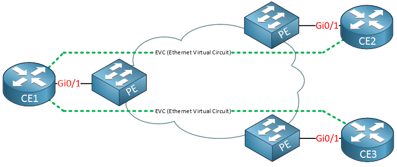
Yes that is correct, when routers are used as CE devices (as shown in your diagram), Layer 2 connectivity is extended only between the CE router interfaces themselves, not to devices behind them. This is intentional and by design.
Even though the technology is typically a Layer 2 transport medium, the goal in most Metro Ethernet deployments is NOT to simply create one giant Layer 2 network spanning multiple offices, but rather to use the Layer 2 Metro Ethernet service as a simple, reliable transport medium for Layer 3 (routed) traffic between sites. So you would typically put routers on either end of your link, and create Layer 3 connectivity between those routers, and ensure your routing on those devices allows traffic to be sent from your networks behind the CEs (on the customer side). It’s simply a matter of design. Does that make sense?
I hope this has been helpful!
Laz
Hello Laz.-
Thank you so much! One final question
What are some use cases of having the SP implement multiple E-lines? Honestly, if you want to connect more sites, wouldn’t you just use E-LAN or Hub and Spoke? What exactly is the benefit of having multiple E-Lines?
David.
Hello David
Technically speaking, E-LAN is a much more elegant solution when you have multiple sites. However, there are cases where you would choose to use multiple E-line links in a hub and spoke arrangement. The most significant one is cost. E-Lines are typically much cheaper than E-LAN solutions. If you only need two or three spokes, it may be worth purchasing individual E-lines. Secondly, for smaller networks, it may be easier for initial scaling. It’s probably easier to add or remove individual E-line connections without needing to reconfigure the entire service.
Small businesses would typicaly start off with a single E-line, and then when they get another branch office, the simplest thing to do is connect a second E-line. Only after three or four spokes would it become necessary (financially and technically) to move to the E-LAN solution.
There are additional benefits as well, including the fact that each E-line in a hub-and-spoke topology ensures traffic isolation between site pairs, and the ability to employ individual bandwidth and QoS control per E-line. Of course, these can be achieved with E-LAN as well, but maybe not as simply and easily.
I hope this has been helpful!
Laz