The NSSA area is an OSPF area where you know there are no other OSPF routers participating in OSPF beyond this interface, however, you know that there is an ASBR router found within that area. An ASBR is a router that connects to non-OSPF autonomous systems. No OSPF goes beyond this area, however, only other AS information should be relayed here. You can find out a more comprehensive explanation from Cisco at this Cisco documentation.
Having a totally stubby area doesn’t mean that that area will not be able to communicate with other OSPF areas. Inter area communication for OSPF occurs via Area Border Routers (ABRs) and all OSPF non-zero areas must have them in order to function. Totally stubby areas can communicate their OSPF state using Type 1 and 2 LSAs, which are intercepted by the ABR and communicated to other OSPF areas.
Totally stubby areas cannot have Autonomous System Boundary Routers (ASBRs) because by definition, a totally stubby are has only a single point of communication with the outside world, specifically, the ABR.
HI,
I have a question on this point.
Doesnt ABR just generate type3 LSA or type 4 to let us know of ASBR.
Now in TSA, the only allowed LSA’s are 1 & 2. So how does ABR help ?
if an ABR is configured with default originate always, my understanding is that route alwas appears as an O *E2 or Type 5 or External route in the downlink routers . But I am seeing it as O *IA in my setup, R1 – R2(ABR) – R3(TSA) , pls let me know why ?
Addtionally in show ip ospf dbs cmd on TSA router , I see only LSA1 and Sumary Net link States (LSA3) being shown, should not LSA 3 be blocked on this ?
Note:THis is a office setup, working since ages, just chekcing my output there.
Thanks
An ABR will generate type 3 LSAs in order to inform other areas of the routes that are found in a particular area. Type 3 LSAs are sometimes known as a summary LSA, that summarises all networks within an area. A type 4 LSA is used to inform other areas of the existence of an ASBR.
Yes, only types 1 and 2 are allowed within the TSA. The ABR doesn’t send any type 3, 4 or 5 LSAs into the TSA, however, it still does send type 3, 4 and 5 LSAs into the other areas it is connected to that are not TSAs, informing them of the networks within the TSA.
When you use the default-information originate command (either with or without the always keyword), the router will generate a type 5 LSA. This means that you should indeed have an O *E2 route in R1 of your topology. Can you verify where you are applying the default-information originate command and where you are seeing the O *IA route and let us know?
You will see only a single “Summary Net Link States” entry which is that of the ABR. This is necessary for the stub router to know how to get out of the area. No other entries will be there since no Type 3 LSAs will enter the area from other ABRs.
The rules apply to NSSAs and totally NSSAs as well. When Rene refers to “stub” areas he means both stub and NSSA, while when he refers to “totally stub areas” he is referring to both totally stub and totally NSSAs.
Hi Rene/Laz,
I am going through the RFC2328 , unable to understand the topology or exact meaning stub networks , can you please relate to this definition on section 2.1 .
2.1. Representation of routers and networks:
#############################################
**FROM**
		+---+            							*
		|RT7|            							*    |RT7| N3|
		+---+            							T   ------------
		  |                							O RT7|   |   |
    +----------------------+							*  N3| X |   |
		  N3
Stub networks


The middle of Figure 1a shows a network with only one attached
router (i.e., a stub network). In this case, the network appears
on the end of a stub connection in the link-state database’s
graph.
#############################################
What is being described in these diagrams is the physical topology on the left and the graph that represents the link state database on the right. The use of ASCII text to create these may affect the clarity, so I will try to clarify.
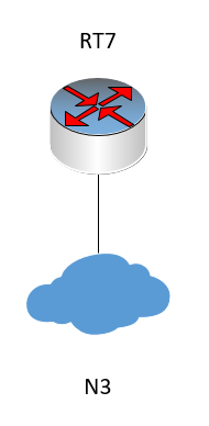
The diagram on the left shows a topology with a router RT7 that is a stub network connected to the “rest of the network” represented by N3. The diagram may look like this:
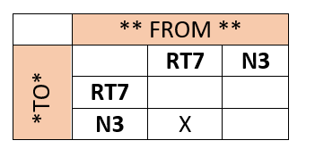
The diagram on the right is a representation of the link state database in the form of a graph or table. These tables have verticies that consist of routers and networks. The specific graph can be represented like so, where RT7 is a router and N3 is a network. Note that in the RFC, each of RT7 and N3 are referred to as vertices of the graph.
Note that networks and routers are represented by vertices. An edge connects two vertices if the intersection of one vertex and another is marked with an X.
Now notice what it says in section 2.1:
The Autonomous System’s link-state database describes a directed graph. The vertices of the graph consist of routers and networks. A graph edge connects two routers when they are attached via a physical point-to-point network. An edge connecting a router to a network indicates that the router has an interface on the network. Networks can be either transit or stub networks. Transit networks are those capable of carrying data traffic that is neither locally originated nor locally destined. A transit network is represented by a graph vertex having both incoming and outgoing edges. A stub network’s vertex has only incoming edges.
So in the above table, we see that the X, also referred to as an “edge” in the RFC, indicates that the “network appears on the end of a stub connection in the link-state database’s graph”. In other words, the graph indicates that the network is a stub network since only the FROM RT7 TO N3 intersection is marked while not the opposite. If the opposite was marked as well (i.e. FROM N3 TO RT7) then the network would be considered a transient network.
These are constructs that are created to more fully understand how a router interprets and understands the link state database, and consequently acts upon the type of network being created. These tables/graphs differ depending on whether the network in question is a stub, a point to point network, or a broadcast NBMA network.
Hello Chandra,
by “Standard area” you probably mean Normal area.
There are main stub area types:
Normal
Stub (+Totally Stubby)
NSSA (+Stub, +Totally Stubby)
When you configure an area and you dont specify it as Stub or NSSA then it is Normal area by default.
Backbone area is just a Normal area, it cannot be Stub or NSSA (otherwise you may filter routes, thus lose connectivity).
Backbone area is always area 0.
Every area has to connect to Backbone (Normal) area, because routes always have to pass
Backbone area to go from one area to other area.
If you are interconnecting two areas, one of them has to be Backbone area (0).
If you have two Backbone areas that are discontinuous, or if you need to extend Backbone area over non-Backbone area, you can use Virtual-Link or Tunnel. But VIrtual-Link is special feature made for this.
What @fugazz says is correct. Just a note here that the what Cisco refers to as a Normal area, many other vendors/professionals refer to as a standard area, so these terms can be used interchangeably.
Also, many will state that the backbone area is not the same as a normal/standard area. A backbone area is defined as area 0, while a normal/standard area is a non-backbone area that does not fall into any other category (stub, totally stubby, NSSA etc).
The thing is that the terms normal/standard are not actually defined in the OSPF RFC so there is some flexibility.
Ahaa, so thats the thing here. People are refering to non-backbone area, that is not a stub or nssa as Standard area, good to know. I was learning OSPF from materials that did not used “standard” in terminology at all. Thanks for pointing this out.
OSPF uses two multicast addresses, specifically, 224.0.0.5 for all OSPF routers, and 224.0.0.6 for all Designated routers. These addresses are used to exchange hello packets and LSAs. Which address is used for which purpose depends on the network topology and the implementation of OSPF. Take a look at this post for more info.
During cisco test I’ve had a question below.
" Which OSPF areas prevent LSA type 4, LSA type 5? ( choose two)"
Possible answers:
NSSA
Total Stubby area
Stubby area
NSSA Totally Stub
I think the answers are Total Stubby and Stubby because in these areas no ASBR allowed.
But according the Cisco guide the 2nd answer should be NSSA Totally Stub.
I’m confusing a bit. Anybody clatify me?
Hello Boris,
your mentor is trying to be very sneaky with this question. All the answers are blocking LSA Type 4+5, but the area types with “Totally” in name are blocking LSA Type 3 on top of LSA Type 4+5. Thus right answer from my point of view is:
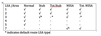
The question is not completely clear, as it does not clarify what it means by “prevent type 4 and type 5”. Does it mean that those LSA types should not exist within the stub area? If so, then all of them should be correct. Take a look at the following table:
However, if we take the question to mean “prevent ONLY type 4 and type 5 LSAs and not Types 1, 2 and 3”, then the answer would be NSSA area and Stubby area as @fugazz suggested. The important thing here is to understand the functionality of the LSAs and apply that to any question that may arise in the exam.