Hi,
If i have 10 Mbps leased-line connect HQ and Branch and i set up InterSrv or DiffSrv between my 2 edge router . QoS for high priority for a service , example http
1- Qos by DiffSrv : When no congestion on Leased-line ( traffic < 10 Mbps), Qos no affect ? or http traffic going to high priority only when have congestion ?
2- QoS by InterSrv : If i config 2 Mbps for RSVP, allway have only 2 Mbps for http traffic , if over 2 Mbps, it drop . Others traffic can using 8 Mbps ?
I have a question on rather Integrated Services (RSVP) can be used in MPLS to identify Real Time Protocol (RTP) traffic like voice or video to give it preference over other traffic. I read your explanation on Resource Reservation, and Admission Control. I’m not understanding how RSVP is used to give RTP traffic that is sensitive to packet loss, jitter, and latency priority over other traffic. Could you explain how this can be done?
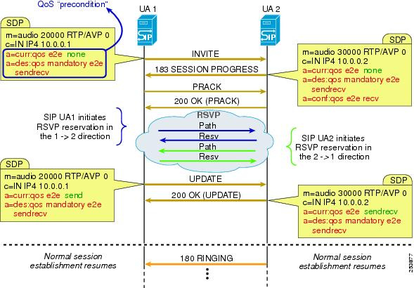
RSVP is used in Cisco Unified Communications architecture in a feature called Call Admission Control (CAC) makes a bandwidth reservation using RSVP along the full length of the path between the two communicating endpoints. Look at the following diagram that comes from Cisco documentation (the link to this document is shown further below).
There is a SIP session that is initiated between two user agents (UAs). These can be phones, gateways, conference bridges etc, anything that will terminate a SIP session. The SIP session begins with INVITE, SESSION PROGRESS, and PRACK OK messages between the two devices. Once that is done, the SIP UA1 initiates an RSVP reservation to UA2. This process involves all RSVP enabled routers between the two devices. Once that has successfully been established, the SIP session continues with an exchange of UPDATE messages, and then the phone rings.
So RSVP takes place chronologically between the initialization of the SIP session and the beginning of the actual telephony communication starting with the ringing of the phone.
This whole mechanisms is a subset of a broader concept of CAC which is fundamental for Cisco’s implementation of IP telephony. You can find out more information about this specific portion of CAC at the following link:
Also, a very elegant explanation of RSVP and how it works can be found in the same document at this location:
Laz,
Thanks for the detailed explanation. It makes since. The documents are also helpful also. I’m going over them now to get a better understanding of RSVP.
Can i do a reservation let’s say for a server behind a particular router? On your example you have R1 thru R4 and a reservation from 1 to 4 on telnet. Instead of include the IP assign to an interface can i use the IPs behind a particular router?
In this lesson, Rene is using the sender-host and reservation-host commands which are used to simulate a host generating RSVP PATH messages and a host generating RSVP RESV messages respectively. These are used to simulate such hosts particularly for debugging purposes.
If you were to include a server (the RSVP sender) and a client (the RSVP receiver) then you would have to enter both the sender and the receiver into the RSVP database with the required parameters (IP address, ports, bandwidth etc…). More about how this is achieved can be found at the following Cisco documentation:
Yes, the way it is explained is a little bit confusing. Let me try to clarify.
Let’s assume we’re looking at video server sending video data to a host, and the video server wants to reserve bandwidth along the path to the host. It is assumed that all routers in between the server and the host are enabled with RSVP.
The server sends a PATH message to the host. This message includes both the source and destination IP (server and host) of the traffic that requires the reservation, as well as the amount of bandwidth to be reserved. This information is stored in each RSVP node that receives and forwards the PATH message.
Once the PATH message reaches the host, it responds with a RESV message. This RESV message will trace the path backwards to the sender. The message must go hop-by-hop in order to ensure that the reverse path being taken is the same as the initial path This is necessary, because only those nodes in that particular path have stored the relevant data in their RSVP databases. For this reason, the RESV message is sent from router to router, with source and IP destination addresses those of the routers themselves. The ultimate destination of the RESV packet is known, since this information is found within the RSVP database that was originally created using the PATH message, so RSVP has the necessary information to ensure that the RESV packet will reach the server.
When it says “…the IP destination address of a RESV message is the IP address of the previous-hop node, obtained from the RSVP path state of each node” what it is saying is that as the RESV message goes from node to node, the destination address of that RESV is the next router in the return path. The text refers to this next router as the “previous hop node” from the point of view of the direction of the initial PATH message.
The wording in the book is ambiguous, as the terms “source” “destination” and “previous hop node” are not being used clearly, and introduce confusion.
Yes i guess it is a typo in the book
since the first “last” RSVP RESV messages (on the far left on the picture says:
FROM: 10.1.1.1 TO:10.3.3.1 TCP DPORT 23 SPORT 12345 Previous HOP 10.1.1.1
(The client to the far left is 10.1.1.1)
because the client cant be the last hop node (before it returns to the client )
I never experied so much error in a OFFICAL Cert Guide before…
its very time consuming for a person that trying to learn from scratch.
Im very thankful to this community.
Is the traffic flowing from right to left on the picture (RSVP Path State) or is the boxes with the source adresses just a ilustration that where the traffic origininated ?
think im still litte confused by this book
EDIT:
I think i understand
The boxes with the source ip is the traffic flowing from left to right (like the initial RSVP Path messages)
but I got confused since the arrows was pointing in the oposit direction (right to left)
I thought the boxes on the images was for the RESV message… since they where linked in to the picture with the (reversed trafic flow).
This does happen from time to time in various certification guides. I’m happy however that you find the NetworkLessons community helpful.
Yes, you’ve got it. It’s a little difficult to keep the directions straight in your head. Just remember that the initiator and sender of the data sends the PATH message, and the receiver sends the RESV message. The PATH message travels in the same direction as the data from the initiator.
When using the ip rsvp sender-host command, the last two entries specify the average bit-rate in kbps that is to be reserved, and the maximum burst size, again in kbps. The burst size indicates the kbps beyond the average bit rate that is allowed.
So with a bit rate of 64 kbps and a maximum burst size of 32 kbps, such a configuration can support 64 kbps continually, and occasionally (64 + 32) 96 kbps bursts.
Note that this command is used to simulate a host generating an RSVP path message, essentially reserving the path with the specific parameters indicated. You can find more information bout this command here:
RSVP for MPLS-TE is an extensive subject that may require several lessons! You can always go to the Member Ideas page and suggest that Rene create a lesson on this topic. You may find that others have suggested it as well, and if so, you can add your voice to theirs.
In the meantime, you can take a look at the following Cisco documentation that details the use of RSVP for MPLS-TE and includes examples:
Hi all,
I am doing the same topology in the lesson in GNS3. In R1 instead of tcp and port 23 i configured below:
ip rsvp sender-host 192.168.34.4 192.168.12.1 1 0 0 1 1
My flow matches ICMP (protocol number with value 1) and reservation is for 1kbps. In all links i have mtu 9216. A ping from R1 specifying the size to 9000 shouldn’t be dropped because the flow is only 1kbps? I still have replies on that ping. Am i missing something?