Hello Thierry
Take a look at this Cisco documentaiton. I believe it is quite thorough in its explanations:
I hope this has been helpful!
Laz
Hello Thierry
Take a look at this Cisco documentaiton. I believe it is quite thorough in its explanations:
I hope this has been helpful!
Laz
Hello Laz,
With respect to your pros and cons, I was able to setup the tunnels with the commands below
tunnel mode ipsec ipv4
tunnel protection ipsec profile ipsec
while running ospf and was able to establish neighbourship over the tunnel and have my pings encrypted. I am using IOSv 15.6.
Any thoughts on this with regarding multicast over ipsec tunnel mode and not GRE.
Hello Tariq
You touch on several issues with your post. First of all, IPSec direct encapsulation supports only unicast traffic. It has been designed to provide connections between only two devices, so multicast is problematic. In order to get multicast (and thus routing protocols such as OSPF which leverage multicast to operate) to function, you essentially have two choices:
The first is a somewhat more legacy solution, although it works very well. GRE supports multicast so OSPF and other routing protocols can function. The second, which you configured in your setup, is considered a newer method of implementation for site-to-site VPNs and is preferable due to the fact that it is simpler to employ, since you don’t have to set up complex access lists and crypto maps to define the traffic to encrypt.
Both will get you the result you need for multicast traffic, however, the latter is the simpler and more elegant choice.
I hope this has been helpful!
Laz
Hello Lazaros,
I’m stuck in this topic related lab. I’m trying to make an IPsec site to site connection between a CSR (on AWS) and a cyberoam FW (on prem). Since in AWS VPC NATS the traffic to CSR, therefore the packets are encapsulated over UDP on port 4500. The tunnels both side comes up however I’m not able to ping the tunnel interface nor the local subnets behind the CSR and Cyberoam FW.
However if the NAT-T is not assumed (in my lab) i.e. CSR interface is having static public ip and Cyberoam FW is also having static public IP then the static tunnel interface comes up and able to ping each other and also BGP adjacency forms.
show crypto isa sa

Interface: Tunnel1
Profile: IPROF
Session status: UP-ACTIVE
Peer: 192.4.10.2 port 4500
  Session ID: 0
  IKEv1 SA: local 10.11.0.2/4500 remote 192.4.10.2/4500 Active
  Session ID: 0
  IKEv1 SA: local 10.11.0.2/4500 remote 192.4.10.2/4500 Active
  IPSEC FLOW: permit ip 0.0.0.0/0.0.0.0 0.0.0.0/0.0.0.0
        Active SAs: 2, origin: crypto map
CSR2#sh cry ip sa peer 192.4.10.2
interface: Tunnel1
Crypto map tag: Tunnel1-head-0, local addr 10.11.0.2
protected vrf: (none)
local ident (addr/mask/prot/port): (0.0.0.0/0.0.0.0/0/0)
remote ident (addr/mask/prot/port): (0.0.0.0/0.0.0.0/0/0)
current_peer 192.4.10.2 port 4500
PERMIT, flags={origin_is_acl,}
#pkts encaps: 31, #pkts encrypt: 31, #pkts digest: 31
#pkts decaps: 8, #pkts decrypt: 8, #pkts verify: 8
#pkts compressed: 0, #pkts decompressed: 0
#pkts not compressed: 0, #pkts compr. failed: 0
#pkts not decompressed: 0, #pkts decompress failed: 0
#send errors 0, #recv errors 0
local crypto endpt.: 10.11.0.2, remote crypto endpt.: 192.4.10.2
plaintext mtu 1422, path mtu 1500, ip mtu 1500, ip mtu idb GigabitEthernet1
current outbound spi: 0x962C9052(2519502930)
PFS (Y/N): N, DH group: none
inbound esp sas:
spi: 0x75622E80(1969368704)
transform: esp-aes esp-sha-hmac ,
in use settings ={Tunnel UDP-Encaps, }
conn id: 2003, flow_id: CSR:3, sibling_flags FFFFFFFF80000048, crypto map: Tunnel1-head-0
sa timing: remaining key lifetime (k/sec): (4607999/3427)
IV size: 16 bytes
replay detection support: Y
Status: ACTIVE(ACTIVE)
inbound ah sas:
inbound pcp sas:
outbound esp sas:
spi: 0x962C9052(2519502930)
transform: esp-aes esp-sha-hmac ,
in use settings ={Tunnel UDP-Encaps, }
conn id: 2004, flow_id: CSR:4, sibling_flags FFFFFFFF80000048, crypto map: Tunnel1-head-0
sa timing: remaining key lifetime (k/sec): (4607998/3427)
IV size: 16 bytes
replay detection support: Y
Status: ACTIVE(ACTIVE)
outbound ah sas:
outbound pcp sas:CSR2#sh cry isa sa
IPv4 Crypto ISAKMP SA
dst src state conn-id status
10.11.0.2 192.4.10.2 QM_IDLE 1002 ACTIVE
192.4.10.2 10.11.0.2 QM_IDLE 1001 ACTIVEplease can you help me troubleshoot where the problem could be?
Thanking in advance.
Hi Zeeshan,
What does your CSR1000V config look like? Even with elastic IP, AWS still uses NAT so you’ll have to deal with NAT-T. I never tried a VPN like this but I can take a look.
Rene
Hi Rene,
Many thanks for your response.
Yes, correct about NAT on AWS, this is why in this lab I later introduced a Router (VPC) performing NAT to simulate the AWS environment.
Please see below config of CSR in this virtual lab on eve. The tunnel 0 which is between CSR and ASAv works as expected. i.e. tunnel IPs are able to ping each other and BGP is forming. But on the other hand CSR and Cyberoam tunnels are UP but can’t ping each other.
Tunnel 0 = ASAv
Tunnel 1 = Cyberoam FW
interface Tunnel1
 ip address 15.15.16.1 255.255.255.0
 ip tcp adjust-mss 1372
 tunnel source GigabitEthernet1
 tunnel mode ipsec ipv4
 tunnel destination 192.4.10.2
 tunnel protection ipsec profile IPSECPROF
 ip virtual-reassembly

interface Tunnel0
 ip address 15.15.15.1 255.255.255.0
 tunnel source GigabitEthernet1
 tunnel mode ipsec ipv4
 tunnel destination 192.2.10.2
 tunnel protection ipsec profile IPSECPROF


  crypto keyring KEY_RING
  pre-shared-key address 0.0.0.0 0.0.0.0 key cisco123
crypto isakmp policy 10
 encr aes
 authentication pre-share
 group 2
crypto isakmp profile IPROF
   keyring KEY_RING
   match identity address 0.0.0.0
crypto ipsec transform-set TSET esp-aes esp-sha-hmac
 mode tunnel
crypto ipsec profile IPSECPROF
 set transform-set TSET
crypto map MYMAP 10 ipsec-isakmp
 set peer 192.3.10.2
 set transform-set TSET
 match address 101


router bgp 65000
 bgp router-id 15.15.15.15
 bgp log-neighbor-changes
 network 10.40.40.0 mask 255.255.255.0
 neighbor 15.15.15.2 remote-as 65001
 neighbor 15.15.16.2 remote-as 65002
 neighbor 15.15.19.2 remote-as 65003
!


ip route 0.0.0.0 0.0.0.0 10.11.0.1
ip route 172.16.16.0 255.255.255.0 Tunnel1
ip route 172.16.19.0 255.255.255.0 Tunnel2
Gateway of last resort is 10.11.0.1 to network 0.0.0.0
S*    0.0.0.0/0 [1/0] via 10.11.0.1
      4.0.0.0/32 is subnetted, 1 subnets
C        4.2.2.2 is directly connected, Loopback4222
      10.0.0.0/8 is variably subnetted, 4 subnets, 2 masks
C        10.11.0.0/24 is directly connected, GigabitEthernet1
L        10.11.0.2/32 is directly connected, GigabitEthernet1
C        10.40.40.0/24 is directly connected, GigabitEthernet2
L        10.40.40.1/32 is directly connected, GigabitEthernet2
      15.0.0.0/8 is variably subnetted, 6 subnets, 2 masks
C        15.15.15.0/24 is directly connected, Tunnel0
L        15.15.15.1/32 is directly connected, Tunnel0
C        15.15.16.0/24 is directly connected, Tunnel1
L        15.15.16.1/32 is directly connected, Tunnel1
C        15.15.19.0/24 is directly connected, Tunnel2
L        15.15.19.1/32 is directly connected, Tunnel2
      172.16.0.0/24 is subnetted, 3 subnets
S        172.16.16.0 is directly connected, Tunnel1
B        172.16.17.0 [20/0] via 15.15.15.2, 00:34:07
S        172.16.19.0 is directly connected, Tunnel2

CSR2#ping 15.15.15.2
Type escape sequence to abort.
Sending 5, 100-byte ICMP Echos to 15.15.15.2, timeout is 2 seconds:
!!!!!
Success rate is 100 percent (5/5), round-trip min/avg/max = 9/10/11 ms
CSR2#

CSR2#ping 15.15.16.2
Type escape sequence to abort.
Sending 5, 100-byte ICMP Echos to 15.15.16.2, timeout is 2 seconds:
.....
Success rate is 0 percent (0/5)
Thanks again for looking into this. I hope you can pin point the issue in the config.
Regards,
Zeeshan
hi ,
with virtual tunnel interface i can use routing protocol …for example if i use ospf protocol under ospf process i need to specify the network of the tunnel or the interface?
thanks !
Hello Andrea
IPSec is not capable of supporting routing protocols due to the fact that it only encapsulates unicast traffic. Dynamic routing protocols such as OSPF or EIGRP will use multicast communication to operate. Based on several instances in Cisco documentation, a static VTI can be used to allow routing protocols to form neighbor adjacencies in order to allow a dynamic routing protocol to function in such a topology. I have also labbed it up and found that OSPF does form a neighbor adjacency between R1 and R2, and the 192.168.1.0/24 and 192.168.2.0/24 subnets are shared between the routers.
Now in order to make the adjacency work, you must include the network of the tunnel interfaces in the network command of OSPF, and not of the actual physical interfaces. Now having said that, in a real world example, the two sites would be remote to each other, and the physical interfaces of the routers would be connected to some edge network device that connects to a WAN or to the internet. The routing between these two physical interfaces is considered already functional (via the ISP providing the WAN or internet connection). Therefore, the dynamic routing protocol should be enabled on the tunnel interface.
Remember that from the point of view of the hosts, there is no 192.168.12.0/24 subnet, and no routing to this subnet is possible. All traffic from H1 to H2 is tunnelled over that subnet, using the 12.12.12.0/24 subnet, therefore the tunnel interfaces should be used in the network command of OSPF.
I hope this has been helpful!
Laz
Hi Zeeshan,
I loaded up your configs on two IOS routers, with a NAT router in between. It works without issues, I can’t see anything wrong with your config.
It can be difficult to find out why IPSec between two different vendor devices doesn’t work. When you look at the packets received/transmitted, do you see anything?
R1#show crypto ipsec sa | include pkts
    #pkts encaps: 153, #pkts encrypt: 153, #pkts digest: 153
    #pkts decaps: 124, #pkts decrypt: 124, #pkts verify: 124
Check whether packets from your IOS router make it to the Cyberoam firewall, and vice versa. This might help to figure out whether this is an IPSec or routing issue. Do you see the UDP header from both ends?
If it’s an IPSec issue, try a debug to see why the packets are refused. If it works without NAT, I’d guess it’s a routing issue.
Rene
thanks nice explanation ![]()
Hi,
I have several questions that hope to get your answers for:
Thank you very much,
Hello Helen
Question 1:
Yes, this is essentially correct.
Question 2:
One of the primary purposes of the introduction of the IPSec VTI was to develop a simplified way of creating an IPSec tunnel over which routing protocols can function. IPSec natively does not support multicast traffic, and therefore, does not support the dynamic establishment of routing protocol neighbors. Although an IPSec GRE tunnel does, it is relatively complicated to set up. This is where the usefulness of the IPSec VTI becomes apparent. There are many scenarios in which it would be useful for a routing protocol, including OSPF, EIGRP, IS-IS, and BGP to name a few, to establish a neighbor adjacency across an IPSec VTI tunnel. It all depends upon the topology, and your specific requirements.
Question 3:
Strictly speaking, routing protocols over a strictly IPSec VPN (without GRE or VTI) will not function because such a link does not support multicast. However, you can configure the OSPF network type to be point to point and non broadcast. BGP, because it doesn’t use multicast to create the peerings, can function over IPSec.
Question 4:
This terminology can be somewhat misleading. There’s really no such thing as IPSec over GRE since GRE doesn’t actually carry IPSec as a payload. It is more correct to say that a GRE tunnel is encrypted using IPSec. However, when these two terms are being used, they refer to the way in which such an encryption is being implemented. “IPSec over GRE” usually refers to the case where a crypto map is directly applied to a GRE tunnel interface. In this case IPSec encryptes the interesting traffic, and then this is encapsulated into the GRE tunnel. An example configuration is:
interface Tunnel0
ip address 10.20.30.40
tunnel source FastEthernet1/0
tunnel destination 10.20.30.43
crypto map vpn
“GRE over IPSec” usually revers to the applying of the crypto map on the physical interface from which the GRE tunnel is sourced. This is where the GRE encapsulated traffic is encrypted using IPSec. This would occur in such a configuration:
interface Tunnel0
ip address 10.20.30.40 255.255.255.0
tunnel source FastEthernet1/0
tunnel destination 10.20.30.43

int  FastEthernet1/0
crypto map vpn
Question 5:
It depends on whether you have configured the crypto map on the tunnel or the physical interface. If the crypto map it is on the tunnel interface, then the interesting traffic should be defined on the tunnel interface. If it is on the physical interface, then the interesting traffic should be defined on the physical interface.
I hope this has been helpful!
Laz
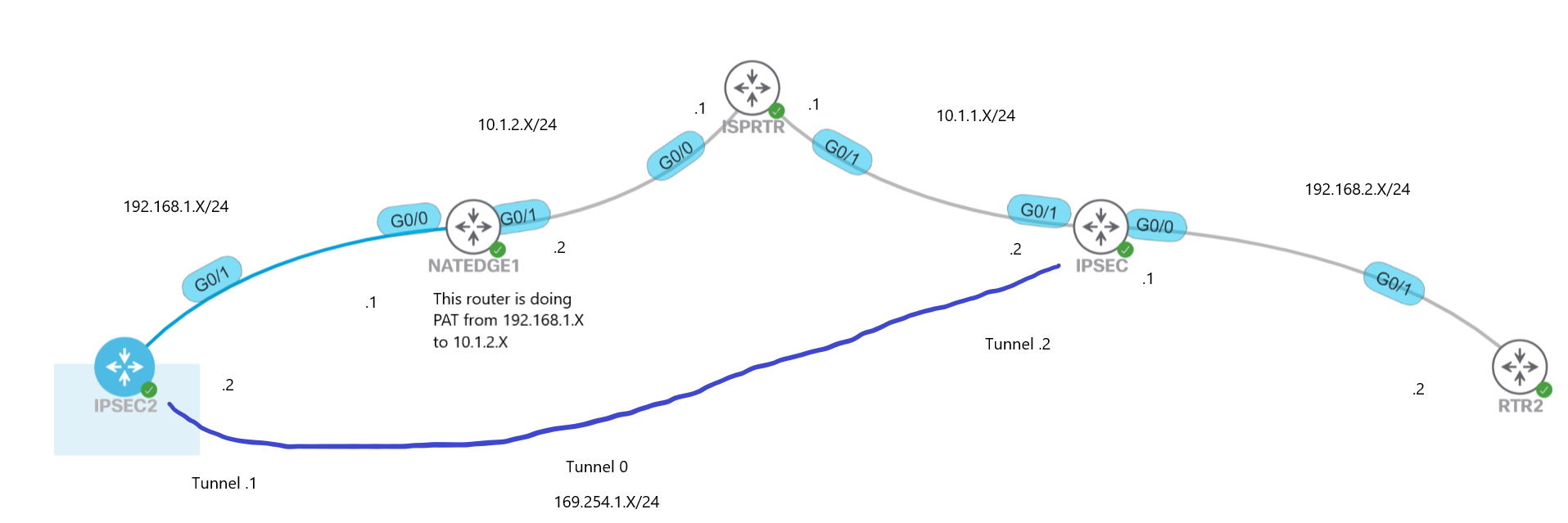
What happens to this configuration if there is a NAT device in front of the device doing the IPSEC tunnel? Here is a picture for an example:
The router on the right trying to do IPSec to the one on the left cannot reach it since NAT. I thought in IOS NAT-T would take care of this automatically. Left router has its peer set to 10.1.1.2 and right router has its peer set to 192.168.1.2. NATEDGE router has default route to 10.1.2.1, IPSEC router has default up to 10.1.1.1. Both IPSEC2 and RTR2 have default routes to the router above them. NAT is working correctly so IPSEC2 router can connect to IPSEC router when doing a simple ping from IPSEC2 router to 10.1.1.2 (this shows that IPSEC2 router can reach IPSEC router for VPN connection).
This may all seem silly however the end goal here is to mock up a remote site connecting to the main office or something to that degree. Main site would be the router on the right and the left side would be a branch office… The branch office wants a secure connection to subnets within the main site. But the branch site is running NAT in front of there VPN connection.
Any thoughts would be appreciated,
Alan
Update:
Once I pointed all the configs on the IPSEC router to 10.1.2.2 the tunnels came up and routing seems to be working. So things are now working as I thought they should. As a side note NAT stats are showing the translation happening with port 4500 for NAT-T.
Hello Alan
This doesn’t seem silly at all. It’s this kind of experimentation that helps you gain a deeper understanding of the inner workings of these kinds of mechanisms.
As far as traversing NAT is concerned, yes NAT-T should be able to detect NAT and deal with successfully creating the IPSec tunnel in such a scenario. Since this is failing in your case, you will have to investigate to see where the problem lies.
I suggest you take a look at these two NetworkLessons notes and the links that they contain. If you get stuck along the way, let us know so that we can help you further in the troubleshooting process.
I hope this has been helpful!
Laz
The static ipsec vpn vti lesson example doesn’t seem to work on my Cisco 8000V routers and it may be a misconfig on my side, but tunnels can’t reach each other when connected back to back in gns3
Router PE1:
pe1#show interfaces tunnel0
Tunnel0 is up, line protocol is down
  Hardware is Tunnel
  Internet address is 192.168.1.1/30
  MTU 10000 bytes, BW 100 Kbit/sec, DLY 50000 usec,
     reliability 255/255, txload 1/255, rxload 1/255
  Encapsulation TUNNEL, loopback not set
  Keepalive not set
  Tunnel linestate evaluation down - no output interface
  Tunnel source 172.16.1.1, destination 192.168.1.2
  Tunnel protocol/transport IPSEC/IP
  Tunnel TTL 255
  Tunnel transport MTU 1500 bytes
  Tunnel transmit bandwidth 8000 (kbps)
  Tunnel receive bandwidth 8000 (kbps)
  Tunnel protection via IPSec (profile "vti-1")
CE1:
ce1#show interfaces tunnel0
Tunnel0 is up, line protocol is down
  Hardware is Tunnel
  Internet address is 192.168.1.2/30
  MTU 10000 bytes, BW 100 Kbit/sec, DLY 50000 usec,
     reliability 255/255, txload 1/255, rxload 1/255
  Encapsulation TUNNEL, loopback not set
  Keepalive not set
  Tunnel linestate evaluation down - no output interface
  Tunnel source 172.16.1.2, destination 192.168.1.1
  Tunnel protocol/transport IPSEC/IP
  Tunnel TTL 255
  Tunnel transport MTU 1500 bytes
  Tunnel transmit bandwidth 8000 (kbps)
  Tunnel receive bandwidth 8000 (kbps)
  Tunnel protection via IPSec (profile "vti-1")
  Last input never, output never, output hang never
Config PE1:
interface Tunnel0
 ip address 192.168.1.1 255.255.255.252
 load-interval 30
 tunnel source 172.16.1.1
 tunnel mode ipsec ipv4
 tunnel destination 192.168.1.2
 tunnel protection ipsec profile vti-1
end
Config CE1:
interface Tunnel0
 ip address 192.168.1.2 255.255.255.252
 load-interval 30
 tunnel source 172.16.1.2
 tunnel mode ipsec ipv4
 tunnel destination 192.168.1.1
 tunnel protection ipsec profile vti-1
end
CRYPTO PE1:
crypto isakmp policy 2
 encryption aes 256
 hash sha
 authentication pre-share
 group 14
crypto isakmp key cisco address 172.16.1.2
!
!
crypto ipsec transform-set uni-perf esp-aes 256 esp-sha-hmac
 mode tunnel
!
!
crypto ipsec profile vti-1
 set security-association lifetime kilobytes disable
 set security-association lifetime seconds 86400
 set transform-set uni-perf
 set pfs group2
CRYPTO CE1:
crypto isakmp policy 2
 encryption aes 256
 hash sha
 authentication pre-share
 group 14
crypto isakmp key cisco address 172.16.1.1
!
!
crypto ipsec transform-set uni-perf esp-aes esp-sha-hmac
 mode tunnel
!
!
crypto ipsec profile vti-1
 set security-association lifetime kilobytes disable
 set security-association lifetime seconds 86400
 set transform-set uni-perf
 set pfs group2

I setup static routes on both but they don't show in the default vrf route table:

ce1(config)#ip route 192.168.1.0 255.255.255.252 tunnel0
interface GigabitEthernet1
 ip address 172.16.1.2 255.255.255.252
 negotiation auto
 no mop enabled
 no mop sysid
end
pe1(config)#ip route 192.168.1.0 255.255.255.252 tunnel0
interface GigabitEthernet1
 ip address 172.16.1.1 255.255.255.252
 negotiation auto
 no mop enabled
 no mop sysid
end
Hello Shane
It looks like your tunnel source and tunnel destination IP addresses are incorrect. The tunnel destination address looks like it’s going to the same subnet as the IP address of the tunnel itself on both ends of the tunnel. If your routers are directly connected, the tunnel source and destination should be on the same subnet.
Take a look at the lesson’s configurations and try to create a corresponding configuration with the appropriate changes in the IP addresses.
I hope this has been helpful!
Laz
Hi Laz that corrected it thanks for my experiment in default VRF.
I’m now seeking to form the tunnel over a non default VRF, c1 in example below and think i’ve some static routing issue, where it doesn’t seem the local tunnel interface is reachable from the local router. Traceroute to the tunnel interface on the peer makes it to the peer interface, but becomes unreachable after that.
pe1#show run interface tun0
interface Tunnel0
 vrf forwarding c1
 ip address 192.168.1.1 255.255.255.0
 load-interval 30
 tunnel source 172.16.1.1
 tunnel mode ipsec ipv4
 tunnel destination 172.16.1.2
 tunnel vrf c1
 tunnel protection ipsec profile vti-1
end

pe1#show run int gi1
interface GigabitEthernet1
 vrf forwarding c1
 ip address 172.16.1.1 255.255.255.252
 negotiation auto
 no mop enabled
 no mop sysid
end

pe1#show ip route vrf c1
Gateway of last resort is not set
      2.0.0.0/8 is variably subnetted, 2 subnets, 2 masks
C        2.2.2.0/24 is directly connected, GigabitEthernet2.2
L        2.2.2.1/32 is directly connected, GigabitEthernet2.2
      9.0.0.0/32 is subnetted, 2 subnets
C        9.9.9.1 is directly connected, Loopback0
S        9.9.9.2 [1/0] via 2.2.2.20
      99.0.0.0/32 is subnetted, 1 subnets
B        99.99.99.99 [200/0] via 9.9.9.2, 09:14:20
      100.0.0.0/32 is subnetted, 1 subnets
C        100.100.100.100 is directly connected, Loopback2
      172.16.0.0/16 is variably subnetted, 2 subnets, 2 masks
C        172.16.1.0/30 is directly connected, GigabitEthernet1
L        172.16.1.1/32 is directly connected, GigabitEthernet1
      192.168.1.0/32 is subnetted, 1 subnets
S        192.168.1.2 [1/0] via 172.16.1.2

pe1#traceroute vrf c1 192.168.1.2
Type escape sequence to abort.
Tracing the route to 192.168.1.2
VRF info: (vrf in name/id, vrf out name/id)
  1 172.16.1.2 2 msec 2 msec 1 msec
  2 172.16.1.2 !H  *  !H
pe1#
I can ping the remote physical interface that the tunnel is created with from both sides, Gig1 but the tunnel doesn’t come online.
pe1#show run interface tun0
Building configuration...

Current configuration : 235 bytes
!
interface Tunnel0
 vrf forwarding c1
 ip address 192.168.1.1 255.255.255.0
 load-interval 30
 tunnel source 172.16.1.1
 tunnel mode ipsec ipv4
 tunnel destination 172.16.1.2
 tunnel vrf c1
 tunnel protection ipsec profile vti-1
end

pe1#show run int gi1
Building configuration...

Current configuration : 140 bytes
!
interface GigabitEthernet1
 vrf forwarding c1
 ip address 172.16.1.1 255.255.255.252
 negotiation auto
 no mop enabled
 no mop sysid
end

pe1#show ip route vrf c1

Routing Table: c1
Codes: L - local, C - connected, S - static, R - RIP, M - mobile, B - BGP
       D - EIGRP, EX - EIGRP external, O - OSPF, IA - OSPF inter area
       N1 - OSPF NSSA external type 1, N2 - OSPF NSSA external type 2
       E1 - OSPF external type 1, E2 - OSPF external type 2, m - OMP
       n - NAT, Ni - NAT inside, No - NAT outside, Nd - NAT DIA
       i - IS-IS, su - IS-IS summary, L1 - IS-IS level-1, L2 - IS-IS level-2
       ia - IS-IS inter area, * - candidate default, U - per-user static route
       H - NHRP, G - NHRP registered, g - NHRP registration summary
       o - ODR, P - periodic downloaded static route, l - LISP
       a - application route
       + - replicated route, % - next hop override, p - overrides from PfR
       & - replicated local route overrides by connected

Gateway of last resort is not set

      2.0.0.0/8 is variably subnetted, 2 subnets, 2 masks
C        2.2.2.0/24 is directly connected, GigabitEthernet2.2
L        2.2.2.1/32 is directly connected, GigabitEthernet2.2
      9.0.0.0/32 is subnetted, 2 subnets
C        9.9.9.1 is directly connected, Loopback0
S        9.9.9.2 [1/0] via 2.2.2.20
      99.0.0.0/32 is subnetted, 1 subnets
B        99.99.99.99 [200/0] via 9.9.9.2, 09:14:20
      100.0.0.0/32 is subnetted, 1 subnets
C        100.100.100.100 is directly connected, Loopback2
      172.16.0.0/16 is variably subnetted, 2 subnets, 2 masks
C        172.16.1.0/30 is directly connected, GigabitEthernet1
L        172.16.1.1/32 is directly connected, GigabitEthernet1
      192.168.1.0/32 is subnetted, 1 subnets
S        192.168.1.2 [1/0] via 172.16.1.2
pe1#trace
pe1#traceroute vr
pe1#traceroute vrf c1 192.168.1.2
Type escape sequence to abort.
Tracing the route to 192.168.1.2
VRF info: (vrf in name/id, vrf out name/id)
  1 172.16.1.2 2 msec 2 msec 1 msec
  2 172.16.1.2 !H  *  !H
pe1#
Hello Shane
What you are attempting to configure is “VRF-Aware IPsec”. This requires additional configurations and has particular restrictions in order to get it to work. You can find out more about it at the following Cisco documentation:
Take a look at the various configuration options and if you have further questions, let us know!
I hope this has been helpful!
Laz
Hi All,
If running routing protocol such as OSPF through the VTI tunnel, does it need a static route to direct the traffic to use the VTI?
Thanks
Hello Wilson
VTI supports multicast, so you can simply use any routing protocol in such a scenario without the need to configure a static route. OSPF as well as other routing protocols can be configured without any special considerations.
I hope this has been helpful!
Laz