MPLS Layer 3 VPN Explained

Thanks for the reply Rene.

Yes I agree, I may have mixed up the CE/PE terminoligies, may be because CE routers are managed by us and the PE routers are ISP managed.

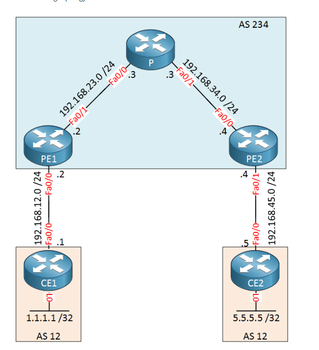
In my scenario, I have VRFs configured on CE1/CE2 routers, and I am not able to ping from VRF end to end. We are using eBGP bet CE1-PE1 and PE2-CE2.

I tried using OSPF bet CE1-PE1 and PE2-CE2, and I am able to ping VRFs end-to-end (VRF CE1 to VRF on CE2) i.e from CustA route to Cust-RTR route. But with eBGP, it does not work.

Yes, I did redistribute connected under the address-family ipv4 and I can see the route under ‘sh ip bgp vpnv4 all’ but not on the global routing bgp table ‘sh ip bgp’. So the PE1 router does not know abt the routes to CustA or CustB.

For instance see below:
On my CE2 router I am learning the route 192.168.253.0, which is VRF interface IP addr of CE1.

CE2#sh ip bgp vpnv4 all
BGP table version is 8, local router ID is 30.30.30.30
Status codes: s suppressed, d damped, h history, * valid, > best, i - internal,
              r RIB-failure, S Stale, m multipath, b backup-path, f RT-Filter,
              x best-external, a additional-path, c RIB-compressed,
Origin codes: i - IGP, e - EGP, ? - incomplete
RPKI validation codes: V valid, I invalid, N Not found

     Network          Next Hop            Metric LocPrf Weight Path
Route Distinguisher: 1:1 (default for vrf C38)
 *>  9.9.9.9/32       0.0.0.0                  0         32768 ?
 *>  192.168.253.0    192.168.0.10             0             0 64520 ?
Route Distinguisher: 2:2 (default for vrf C39)
 *>  80.80.80.80/32   192.168.0.10                           0 64520 64521 ?
 *>  192.168.251.0    192.168.0.10                           0 64520 64521 ?
CE2#
CE2#
CE2#ping vrf C38 192.168.253.245
Type escape sequence to abort.
Sending 5, 100-byte ICMP Echos to 192.168.253.245, timeout is 2 seconds:
.....
Success rate is 0 percent (0/5)
CE2#
CE2#traceroute vrf C38 192.168.253.245
Type escape sequence to abort.
Tracing the route to 192.168.253.245
VRF info: (vrf in name/id, vrf out name/id)
  1  *  *  *
  2  *  *  *
  3  *  *
CE2#

Also, on CE2 I have LO1 9.9.9.9 in vrf C38 and I learn the route on CE1 in vrf C38. But cant ping ir from CE1. See below:

CE1#sh ip bgp vpnv4 all
BGP table version is 7, local router ID is 20.20.20.20
Status codes: s suppressed, d damped, h history, * valid, > best, i - internal,
              r RIB-failure, S Stale, m multipath, b backup-path, f RT-Filter,
              x best-external, a additional-path, c RIB-compressed,
Origin codes: i - IGP, e - EGP, ? - incomplete
RPKI validation codes: V valid, I invalid, N Not found

     Network          Next Hop            Metric LocPrf Weight Path
Route Distinguisher: 1:1 (default for vrf C38)
 *>  9.9.9.9/32       192.168.0.18             0             0 64530 ?
 *>  70.70.70.70/32   192.168.253.50           0             0 64522 ?
 *   192.168.253.0    192.168.253.50           0             0 64522 ?
 *>                   0.0.0.0                  0         32768 ?
Route Distinguisher: 2:2 (default for vrf C39)
 *>  80.80.80.80/32   192.168.251.70           0             0 64521 ?
 r>  192.168.251.0    192.168.251.70           0             0 64521 ?
CE1#
CE1#ping vrf C38 9.9.9.9
Type escape sequence to abort.
Sending 5, 100-byte ICMP Echos to 9.9.9.9, timeout is 2 seconds:
.....
Success rate is 0 percent (0/5)
CE1#tra
CE1#traceroute vrf C38 9.9.9.9
Type escape sequence to abort.
Tracing the route to 9.9.9.9
VRF info: (vrf in name/id, vrf out name/id)
  1  *  *  *
  2  *  *  *
  3  *  *  *
  4  *  *  *
  5
CE1#

In this scenario, I am doing eBGP bet CE1-PE1, iBGP bet PE1-PE2 and eBGP bet PE2-CE2. Below is the bgp config on CE1 and CE2:

CE1#sh run | s bgp
router bgp 64520
 bgp log-neighbor-changes
 neighbor 192.168.0.9 remote-as 3549
 neighbor 192.168.0.18 remote-as 64530
 neighbor 192.168.0.18 ebgp-multihop 7
 !
 address-family ipv4
  redistribute connected
  neighbor 192.168.0.9 activate
  no neighbor 192.168.0.18 activate
 exit-address-family
 !
 address-family vpnv4
  neighbor 192.168.0.18 activate
  neighbor 192.168.0.18 send-community extended
 exit-address-family
 !
 address-family ipv4 vrf C38
  redistribute connected
  neighbor 9.9.9.9 remote-as 64530
  neighbor 9.9.9.9 ebgp-multihop 4
  neighbor 9.9.9.9 activate
  neighbor 192.168.253.50 remote-as 64522
  neighbor 192.168.253.50 activate
 exit-address-family
 !
 address-family ipv4 vrf C39
  neighbor 192.168.251.70 remote-as 64521
  neighbor 192.168.251.70 activate
 exit-address-family
CE1#

    CE2#sh run | s bgp
    router bgp 64530
     bgp log-neighbor-changes
     neighbor 192.168.0.10 remote-as 64520
     neighbor 192.168.0.10 ebgp-multihop 7
     neighbor 192.168.0.17 remote-as 3549
     !
     address-family ipv4
      redistribute connected
      no neighbor 192.168.0.10 activate
      neighbor 192.168.0.17 activate
     exit-address-family
     !
     address-family vpnv4
      neighbor 192.168.0.10 activate
      neighbor 192.168.0.10 send-community extended
     exit-address-family
     !
     address-family ipv4 vrf C38
      redistribute connected
      neighbor 192.168.253.245 remote-as 64520
      neighbor 192.168.253.245 ebgp-multihop 4
      neighbor 192.168.253.245 activate
     exit-address-family
    CE2#

When I use OSPF bet CE1-PE1, PE1-PE2, and PE2-CE2 and use mpls ip on all the non-vrf interfaces between, it just works fine. I am able to ping vrfs end-to-end

CE2#sh ip bgp vpnv4 all
BGP table version is 15, local router ID is 30.30.30.30
Status codes: s suppressed, d damped, h history, * valid, > best, i - internal,
              r RIB-failure, S Stale, m multipath, b backup-path, f RT-Filter,
              x best-external, a additional-path, c RIB-compressed,
Origin codes: i - IGP, e - EGP, ? - incomplete
RPKI validation codes: V valid, I invalid, N Not found

     Network          Next Hop            Metric LocPrf Weight Path
Route Distinguisher: 1:1 (default for vrf C38)
 *>  10.10.10.10/32   192.168.0.21             0             0 64531 i
 *>i 70.70.70.70/32   20.20.20.20              0    100      0 64522 i
 r>  192.168.0.20/30  192.168.0.21             0             0 64531 ?
 *>  192.168.0.24/30  192.168.0.21             0             0 64531 ?
 *>i 192.168.253.0    20.20.20.20              0    100      0 64522 i
Route Distinguisher: 2:2 (default for vrf C39)
 *>  10.10.10.10/32   192.168.0.26             0             0 64531 i
 *>i 80.80.80.80/32   20.20.20.20              0    100      0 64521 ?
 *>  192.168.0.20/30  192.168.0.26             0             0 64531 ?
 r>  192.168.0.24/30  192.168.0.26             0             0 64531 ?
 *>i 192.168.251.0    20.20.20.20              0    100      0 64521 ?
CE2#
CE2#ping vrf C38 192.168.253.245 source GigabitEthernet1/0
Type escape sequence to abort.
Sending 5, 100-byte ICMP Echos to 192.168.253.245, timeout is 2 seconds:
Packet sent with a source address of 192.168.0.22
!!!!!
Success rate is 100 percent (5/5), round-trip min/avg/max = 80/91/96 ms
CE2#

GigabitEthernet1/0 int is in VRF C38. So it works with OSPF and not with BGP. Would like to know why, since even with BGP both CE1 and CE2 are learning vrf routes but cant ping.

Hello everyone I was wondering if in the following topology


ping between PE1 and CE2 is possible.
PE1 knows how to reach CE2 but CE2 needs a default route pointing to PE2 but as I see on my wireshark PE2 generates a message back to CE2 that the destination (PE1 LOOPBACK) is unreachable and this is not true because PE2 knows how to reach PE1 through the global routing table.
So what is the problem ? Maybe PE2 is looking for PE1 on its vrf routing table and thats why cant route the packet? Would it fix the issue if we use route leaking between the routing - tables?

Hello Hektor

Ping between PE1 and CE2, under normal circumstance, should not be possible. This is because of the reason you state in your post. PE2 is looking for PE1 on its VRF routing table, because all traffic from the customer should be routing using the VRF. Route leaking would allow you to reach PE1 from CE2, but this is a highly unlikely scenario, since ISPs would not want customer equipment to have access to network devices on their internal backbone.

I hope this has been helpful!

Laz

1 Like

Thank you Mr Lazare you are great.

1 Like

Hi
in general what is layer 3 vpn and layer 3 vpn ,
is ipsec vpn is l2 ?

Thanks

Hello Sims

Whenever we say that something is Layer 3, it means that it involves things like IP addresses, routing, NAT and any other mechanisms that occur at that layer. In this particular case, a Layer 3 VPN simply means that the ISP is participating in routing operations and this routing information is shared between the CE and PE devices. In contrast, a layer 2 VPN will just provide a link between two sites that just behaves as if each site is connected to a switchport of the same Layer 2 switch, essentially allowing connectivity between devices at both sites using a single subnet. Any routing that may be required must be achieved by adding a router at the customer premises. Routing in this case would only take place between the two CE routers and would not involve the ISP devices whatsoever.

As for IPSec VPN, IPSec is a layer 3 technology that provides authentication and authorization and a whole host of other security features. This is definitely a layer 3 technology as it functions as a set of companion protocols that offer these features and services.

I hope this has been helpful!

Laz

Hello all

I would like to make a question. In Layer 3 MPLS VPN networks how do Ps forward the packets? I mean the router will not have the destination route in the MPLS forwarding table and routing table. It will see the label value tagged by the MPLS router that forwarded the packet to our P. If the P router has received the same label tag value from more than 1 router through the LDB exchange information process, how does it know where to forward the packet to? Does it see the local interface, where it has received the packet from and associates it with the interface used for the LDP neighborship or something else? Thank you in advance

Best Regards
Markos

Hello Markos,

The P routers don’t do any regular IP routing, they don’t look at the source and/or destination IP addresses in the IP packet. The only they the P router does, is switch based on labels.

The Label Switched Path (LSP) is between the PE router loopback interfaces so the only thing the P router needs to know, is how to reach those loopback interfaces. In the LIB, you can see the labels per neighbor. In the LFIB, you can see the outgoing interface. You can see some examples in this lesson:

Hope this helps!

Rene

Hello,

Question. I have configured my lab just as you explained on MPLS L3VPN configurations page. If PE1-P-PE2 routers are advertising O*E2 static routes in OSPF, is there a way to redistribute the OSPF type 2 static route to CE1 and CE2 via eBGP?

Thank you,

Sang

Hello Sang

Yes, it is possible to have redistribution of these routes to CE1 and CE2. Take a look at this lesson which illustrates how eBGP is used to redistribute such routes into CE1 and CE2 using eBGP.

I hope this has been helpful!

Laz

Hi Rene and staff,
MPLS in a huge lesson to read, so i hope my question has not been answered yet
Essentially, i want to know where are carried these new pieces RD, RT, VPN label
I think MPLS packet looks like below
Image5

  1. are RD and RT carried in NLRI ?
  2. is VPN label carried in L2.5 header ?
  3. LDP is tunneling between PE1 and PE2. Is it right ?
    When GRE is tunneling we have two L3 headers,and the tunnel is the external L3 header with ip source and ip destination
    Is LDP tunneling with the L2.5 header ? I dont understand how exactly LDP is tunneling because we dont have a label source and a label destination
    I hope you will understand my questions
    Regards

Hello Dominique

Both RD and RT are carried as part of the BGP updates that are exchanged between MPLS routers. Take a look at this wireshark capture of a BGP update:

Yes, this is correct. Even in the case where you have two MPLS labels (2 headers), both inner and outer labels will be carried in the MPLS header.

For this one, I think that this Cisco Form thread will be helpful. Take a look and if you have further questions, let us know!
https://learningnetwork.cisco.com/thread/91019

I hope this has been helpful!

Laz

Hi Rene and staff,
thanks Laz for your reply, may i ask another question ?
PE1 and PE2 are peers iBGP; when they exchange packets (whatever types: update, ping, …), MPLS switch the packets along P routers based on the label.
In classic infrastructure (without MPLS) L2 header has to be rewrited as the packet goes from a router to a next router
With MPLS when a label packet starts from PE1 and the destination is PE2, what MAC is used ? is it PE2’s MAC ? that would be logic, so there would be no need to rewrite the L2 header along the P routers; on each P router, just swap the label and forward to the next P router
Please could you clarify this point
Regards

Hello Dominique

For customer traffic routed from one CE to another, yes this is true. For traffic exchanged between the routers themselves, such as BGP updates, CDP, or other control traffic that remains within the AS, they use the IGP to communicate (OSPF, EIGRP, etc,…).

Correct.

As far as the way the MAC addresses are managed, nothing changes. When a router receives a frame, it will always de-encapsulate starting from the lower OSI layers to the upper OSI layers. In order to reach the MPLS label, you must first

  1. read the frame header, strip it off
  2. read the packet header, strip it off
  3. read the MPLS header, do label switching/swaping
  4. encapsulate with the packet header
  5. encapsulate with the frame header (with the new source and destination MAC address)
  6. encode and place on the medium.

Because of the layered approach of the OSI model, what happens with IP addresses and MPLS labels is completely independent of what happens to the MAC addresses.

I hope this has been helpful!

Laz

Hi Rene and staff,
Laz, thank for your reply; i paused my studies in June and i am back again to go deeper with mpls
In MPLS VPN L3 cases that i usually lab with GNS3, there is only one label: the label that is used to switch the packet between the PE routers
Could you help me to lab a situation where i could see a stack of labels ? so i could clarify the pop operation and the delete operation
Regards

Hello Dominique

Welcome back, hope your break was refreshing, and you’re ready for more networking! Rene doesn’t currently have a lab that deals specifically with a stack of labels, beyond what he mentions about the stack in this lesson:


However, you can gain some insight into label stacks from Cisco documentation like this:

This is an over view of MPLS, but the section on label stacking is quite comprehensive and may give you an initial starting point from which to move forward. In any case, if you want Rene to provide a lab or other content concerning MPLS, you can always suggest it at the Lesson Ideas page below:

I hope this has been helpful!

Laz

Hi Rene and staff,
Laz, thank you for your reply: MPLS -the internet protocol journal-Volume 4,Number 3 is a very good source of information
There are some points i can’t clarify about VPN label used for data plane.
Typically for MPLS VPN L3 a two level label stack is used with a VPN label at the bottom of the label stack, is not it?
What i understand is that this label is automatically generated by the egress PE router for each VPNV4 address and advertised to the PE ingress router. Is it right?
But how this label is carried in the control plane ? Is it carried by an extended BGP communities ?
I read somewhere that it was carried as an hidden part of Route Distinguisher ? is it right ?
But when i look at the RD formats (type 0, type1, type2) i can’t see any place for the VPN label.
Could you clarify these points ?
Regards

Hello Dominique

As far as the control plane goes, the VPN label is carred within an attribute of the Network Layer Reachability Information (NLRI) format of MP-BGP. This NLRI contains the RD, the IPv4 prefix, the next hop as well as the VPN label.

If you look at a wireshark output of such an MP-BGP NLRI, you can see these four attributes contained within it:


You can ignore the red boxes. Notice in the Label stack, we have the Label Stack which is the VPN label.

I hope this has been helpful!

Laz

Hi Rene,

I see some kind of contradiction. If RD is a unique characteristic for every route, so on the left side you should have RD 123:10 for one route. On the right side 123:11 for another route of the same customer. But in fact, RD is a unique parameter for the customer. Please, correct me if I am wrong.

Thanks in advance.

Hi Vadim,

The RD is a unique parameter for a customer/site, not for a prefix. With a different RD per customer, we create unique prefixes.

Let’s say we have two customers and they both have network 192.168.1.0/24. Without the RD, there’s no way to differentiate between the two 192.168.1.0/24 networks. With a RD for each customer, we suddenly have two unique VPN routes.

Rene