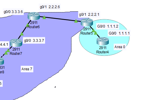
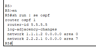
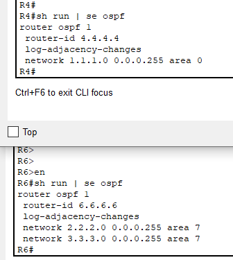
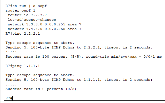
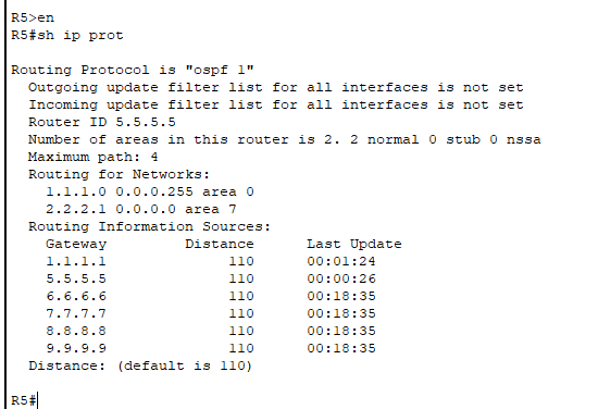
I am using Cisco’s packet tracer for OSPF. My very simple OSPF config allows me to ping from R7 to R6 to R5 to R4, all on area 7. When I change the R5 to R4 connection to Area 0, that does not get sent to the other routers, and the ping fails. In other words, R5 becomes an ABR, left side to Area 7, right side to Area 0. Router 7 can not ping 1.1.1.1 ; I thought the ABR was automatic; do I need to redistribute ? Maybe packet tracer can’t handle it?
I believe my issue is a bug in Packet Tracer; required a router reboot, not just a clear-ip-ospf-process. Comments still welcomed. Thanks.
Hello Jimmy
It is not immediately apparent what the problem in the configuration is, however, there are some fundamental troubleshooting steps that you can take to discover where the issue is.
First of all check to see that neighbor relationships between routers have been successfully established. Looking at the output of the show ip protocols command on R5 it looks likely that these adjacencies have been established correctly, but it’s a good idea to check this explicitly using the show ip ospf neighbor command on all appropriate routers.
Next, you can examine the routing tables of the routers involved. Make sure that the next hop IP provided by the OSPF routes in each router is correct. Check both directions! You may find that the ping actually reaches its destination only to be dropped due to the fact that there is no return route configured.
Finally, additional insight can be gained by looking at the OSPF database. Especially at the ABR router, ensure that the correct LSAs are being generated and stored.
An excellent lesson on troubleshooting OSPF can be found at the following link, that may help you further in the process:
Hopefully, this will give you some insight and inspiration to continue the troubleshooting process. Let us know how you get along!
I hope this has been helpful!
Laz
Thanks Laz. It looks like Packet Tracer required a router reboot; the Clear IP OSPF Process command (on both routers) was insufficient. Problem solved. But it would be nice to have a list of packet tracer bugs; do you know of one? Best.
1 Like
Hello Jimmy
Thanks for sharing your experience, that’s really helpful to the whole community. Bugs can be reported from the Packet Tracer application itself by going to the Help → Report an Issue menu item. The problem is that I haven’t done this in a long time, and from my Packet Tracer version 7.0.0.0306 it opens my browser and takes me to a broken link. I don’t know if newer versions fo the software have this fixed…
Anyway from that site, you were able to view recent bugs and the progress of having them fixed. After a brief search, I was unable to find where the “new” location of bug fixes is.
Update: I just upgraded my packet tracer to 7.3.1 and it still opens a browser page to http://ptbugs.netacad.net/ which is a broken link. Alternatively you can report bugs at the GLobal Support Desk by logging in to Cisco Netacad.com and clicking Help at the top of the page, then selecting Global Support Desk.
If anyone has any info about packet tracer bugs, please feel free to share it here…
I hope this has been at least somewhat helpful… ![]()
Laz
Hi Lazaros,
What is the benefit of setting up the loopback as a 255.255.255.255 and then advertising it with a wildcard of 0.0.0.0? Thank you for answering so many of my previous questions I do apologize I haven’t been on the forum lately to thank you!
interface Loopback0
 ip address 3.3.3.3 255.255.255.255

router ospf 1
 network 3.3.3.3 0.0.0.0 area 1
 network 192.168.13.0 0.0.0.255 area 1
Hello Daniel
When configuring the IP address of an interface, such as a loopback interface, we use the subnet mask to specify the size of the subnet within which the interface resides. In this particular case, a subnet mask of 255.255.255.255 simply says that this interface has a single IP address, and it is the only address in its subnet. This is called a host mask, meaning that there is only a single address in the subnet. This mask can also be denoted using the /32 notation.
Now when configuring the network command under the OSPF configuration, in order to specify the networks participating in OSPF, we must use a wildcard mask. A wildcard mask does the same job as a subnet mask, but it simply does it using ones instead of zeros and zeros instead of ones, in binary of course. You can find out more about a wildcard mask here:
In any case, the wildcard mask that corresponds to the subnet mask of 255.255.255.255 is 0.0.0.0, and this is why it is used in the network command. Rene could have used 0.0.0.255 instead, and this would have worked as well since the IP address of the loopback is within the range specified.
I hope this has been helpful!
Laz
PS No worries about the many questions, that’s what we’re here for!! Always a pleasure!
Great explanation thanks Lazaros !
1 Like
Hello rene/laz,
can u please explain
why osp require all traffic between non-backbone areas to pass through a backbone area(area0)?
Hello Himanshu
This is simply a design issue. In order for OSPF to be able to achieve the scalability that is required, an area 0 backbone is required. For more information, take a look at this NetworkLessons Note on why a backbone area 0 is necessary.
I hope this has been helpful!
Laz
Hello,
I have a doubt regarding OSPF loop prevention.
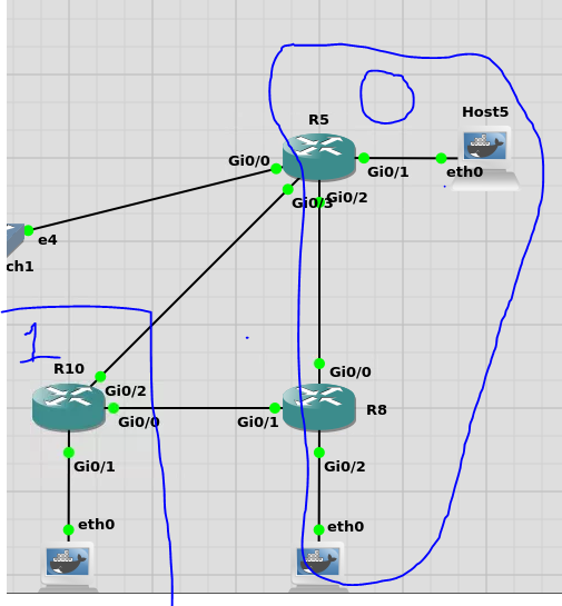
R5 and R8 are in area 0 and they are connected to each other
whereas R10 is in Area 1 and one interface or link of R5 and R8 are directly connected to R10.
My question is since both R5 and R8 are learning the same topology from (R10). How they will communicate with each other to make it a loop free technology ?
“
”
Hello Aditi
Such a topology does not present a problem for OSPF. Whether these routers are in different OSPF areas or the same one, having multiple paths within a topology is perfectly acceptable. The mechanisms used to prevent loops in such cases have to do with the choice of a single path to a particular destination.
For more information on how OSPF operates to prevent loops, take a look at this post:
I hope this has been helpful!
Laz
Hi Laz,
Thanks for responding but i am still confused. I will be really specific over here
R10 has a prefix say ( 10.10.10.10). LSA Type 1 is generated and that prefix is shared to R8 and R5 since one of their interface is in Area 1. R5 and R8 will generate LSA 3 and will send it to each other since they are in area 0. So my understanding is please correct me if i am wrong , why would R5 and R8 take that information from each other since they are already learning the prefix as intra area route?
And if I reverse the area’s now R10 is in area 0 and R5 and R8 in area 1 as per the ABR rule - if ABR learns Type 3 LSA inside non backbone area, ABR ignores that LSA when calculating its own routes?
1 Like
Hi Laz,
Say your got 3 routers in area 0 and 2 routers in area 10 connected by a /29 subnet do we end up with more then one ABR or what happens here? I currently don’t have the routers spare to play around with a setup like this but planning to have soon.
- Adam
Hello Aditi
Let’s take your first scenario. R5 and R8 will generate type 3 LSAs and will flood Area 0 with them. That means that R5 will receive a type 3 LSA from R8, and vice versa. But that doesn’t mean that a loop has occurred. Remember, OSPF is a link-state protocol, and it thus learns the whole topology, so it knows all of the alternate paths from all of the LSAs, but it chooses only a single path to install in the routing table, that is, the best path.
Similarly, if the areas were reversed, the LSA rules that you mention are in place, and these by design, ensure that there is no routing loop. Take a look at the OSPF ABR and Loop Prevention NetworkLessons note for more info on this mechanism.
I hope this has been helpful!
Laz
Hello Adam
First of all, an OSPF router does not belong to a particular area. It is its interfaces that are assigned to specific areas, thus stating that a router belongs to an OSPF area does not clearly describe the topology. More info about this detail can be found at this NetworkLessons note.
Now having said that, you can have a topology where you have two or more ABRs between two OSPF areas. This is an acceptable topology. Using OSPF’s routing mechanisms, it will still be able to choose the best path for specific destinations in both areas without any problems.
This is a simple topology that you can try out using Cisco’s Packet Tracer, or GNS3 if you like, so you don’t need to set up a real topology to experiment with it.
I hope this has been helpful!
Laz
Thank you Laz, I will have a play with this shortly.
- Adam
1 Like
Hello,
I am confused a little. DR/ BDR election exists only in multi access network, not on point-to-point links. But I see in this lesson and prevous one this line “Full/DR; Full/BDR”. How can it be possible, if the topology has only point-to-point links?
Hello Shahlar
It is true that a DR/BDR election won’t take place in a point-to-point network between OSPF routers. However, we must define what “point-to-point” means. OSPF will automatically detect a point-to-point network based on the underlying technology.
For example, a serial connection is considered point-to-point, because, by definition, serial connections can have only one device connected on the opposite end of the circuit. OSPF will interpret an OSPF peering over a serial circuit as a point-to-point network type by default.
However, Ethernet is a multi-access technology, so when OSPF sees this, even if the physical topology is indeed point-to-point, it considers the connection as multiaccess, thus a DR/BDR election takes place.
You can of course change this behavior by simply issuing the ip ospf network command within the OSPF router configuration mode. More about this command can be found here:
I hope this has been helpful!
Laz
1 Like
Hi Laz,
Thank you for this very detailed answer. Now it’s very clear for me.
1 Like