# Rapid Spanning-Tree Configuration
**URL:** https://forum.networklessons.com/t/rapid-spanning-tree-configuration/1139
**Category:** Lessons Discussion
**Created:** [December 27, 2016, 4:29pm UTC](https://forum.networklessons.com/t/rapid-spanning-tree-configuration/1139 "2016-12-27T16:29:05Z")
**Posts on this page:** 20
**Page:** 1
### Author:  [@ReneMolenaar](https://forum.networklessons.com/u/ReneMolenaar)
#### Post date: [December 27, 2016, 4:29pm UTC](https://forum.networklessons.com/t/rapid-spanning-tree-configuration/1139/1 "2016-12-27T16:29:05Z")
This topic is to discuss the following lesson:
> **[Rapid Spanning Tree Configuration](https://networklessons.com/spanning-tree/rapid-spanning-tree-configuration)**
>
> Rapid Spanning-Tree uses a sync mechanism instead of timer-based BPDUs and some other tricks to make it faster than "classic spanning-tree".
---
### Author:  [@mdbetar](https://forum.networklessons.com/u/mdbetar)
#### Post date: [May 12, 2015, 3:58pm UTC](https://forum.networklessons.com/t/rapid-spanning-tree-configuration/1139/2 "2015-05-12T15:58:05Z")
Nice explanation, Rene.
You nicely described in STP, how the affected switch updated CAM table.
When a link fails (Uplink/Backbone) in RSTP environment, how the affected switch will collect MAC?
---
### Author:  [@ReneMolenaar](https://forum.networklessons.com/u/ReneMolenaar)
#### Post date: [May 14, 2015, 5:15pm UTC](https://forum.networklessons.com/t/rapid-spanning-tree-configuration/1139/3 "2015-05-14T17:15:13Z")
Hi Betar,
Here’s an example how the MAC addresses are updated for uplink failures:
> **[Spanning Tree UplinkFast](https://networklessons.com/spanning-tree/spanning-tree-uplinkfast)**
>
> UplinkFast increases spanning tree conversion time. This lesson explains what it is, how it works and how to configure it.
Uplinkfast can be enabled for “classic” STP but a similar mechanism is built-in RSTP.
Backbone fast is also a good read:
[https://networklessons.com/ciscospanning-tree-backbone-fast/](https://networklessons.com/ciscospanning-tree-backbone-fast/)
A similar mechanism is built in for RSTP.
Rene
---
### Author:  [@tkalis](https://forum.networklessons.com/u/tkalis)
#### Post date: [August 31, 2015, 1:05am UTC](https://forum.networklessons.com/t/rapid-spanning-tree-configuration/1139/4 "2015-08-31T01:05:15Z")
Rene,
Hi. In the last part of the lesson you convert switch B to PVST mode - what is the impact to the network - does computer A lose connectivity to the rest of the network outside of switch B for 30 seconds? What about if there was a host connected off of switch A and another host connected off switch B - they would still continue to communicate throughout the change of switch B to PVST mode?
Many thanks,
Thomas
---
### Author:  [@ReneMolenaar](https://forum.networklessons.com/u/ReneMolenaar)
#### Post date: [September 6, 2015, 10:02pm UTC](https://forum.networklessons.com/t/rapid-spanning-tree-configuration/1139/5 "2015-09-06T22:02:39Z")
Hi Thomas,
I just tried this, 3 switches and two hosts (one on SW1 and SW2). If you switch to any of the STP mode, you have donwtime. When I change one switch from RPVST to PVST+ then you see the interfaces going through the listening and learning states again.
When all switches are running PVST+ and I turn one of them into RPVST, you see it sending and waiting for proposals. It’s all compatible but expect your interfaces to be blocked for a moment 🙂
Rene
---
### Author:  [@shanmugasivak](https://forum.networklessons.com/u/shanmugasivak)
#### Post date: [May 4, 2016, 7:57pm UTC](https://forum.networklessons.com/t/rapid-spanning-tree-configuration/1139/6 "2016-05-04T19:57:55Z")
Hi Rene,
Pasting the debug msgs:
```auto
SwitchA#
setting bridge id (which=3) prio 4097 prio cfg 4096 sysid 1 (on) id 1001.0011.bb0b.3600
```
what does it mean ? I’m not able to understand.
---
### Author:  [@andrew](https://forum.networklessons.com/u/andrew)
#### Post date: [May 4, 2016, 9:24pm UTC](https://forum.networklessons.com/t/rapid-spanning-tree-configuration/1139/7 "2016-05-04T21:24:14Z")
Sorry, Shanmugasiva,
I am not understanding what you are asking. Could you ask this another way?
If you are asking what this message means, I can try to help.
`setting bridge id (which=3) prio 4097 prio cfg 4096 sysid 1 (on) id 1001.0011.bb0b.3600`
“cfg 4096”
This means you set (either via spanning-tree vlan 1 4096, or spanning-tree vlan 1 root primary). This is what it means when it says “prio cfg 4096”–the vlan was configured to be priority 4096.
“prio 4097”
However, the actual priority is the configured priority + vlan number. So, in this case, the actual priority is 4097 (4096 + 1, for vlan 1). This is what it means for “prio 4097”
“(on) id 1001.0011.bb0b.3600”
This is the MAC address of the switch where this command was issued.
---
### Author:  [@shanmugasivak](https://forum.networklessons.com/u/shanmugasivak)
#### Post date: [May 5, 2016, 3:50am UTC](https://forum.networklessons.com/t/rapid-spanning-tree-configuration/1139/8 "2016-05-05T03:50:26Z")
Thanks Andrew!
I meant to ask about the priority 4096 and 4097.
From the picture, Switch A has the priority 32768. Why do we represent 4096 here ?
---
### Author:  [@andrew](https://forum.networklessons.com/u/andrew)
#### Post date: [May 5, 2016, 6:07pm UTC](https://forum.networklessons.com/t/rapid-spanning-tree-configuration/1139/9 "2016-05-05T18:07:25Z")
Hi Shanmugasiva,
I suspect this simply might be a case of label in the picture not matching the configured IOS. In one of the outputs from Switch A it says “This bridge is the root” and it lists the Root ID of 4097.
Notice, the same thing is true for Switch B. It says in the text output it says its priority is 8193, but the label in the picture shows 32768.
Good catch!
–Andrew
---
### Author:  [@bkaramazov19](https://forum.networklessons.com/u/bkaramazov19)
#### Post date: [September 20, 2018, 11:16am UTC](https://forum.networklessons.com/t/rapid-spanning-tree-configuration/1139/10 "2018-09-20T11:16:31Z")
Hello Rene,
I have configured a lab connecting three switches on gns3 (SW1,SW2 and SW3). SW1 is the Root switch. They are connected like this:
SW1(e1/3-DP)\>\>\>SW2(e1/3-RP)
SW1(e3/0-DP)\>\>\>SW3(e3/2-RP)
SW2(e3/0-DP)\>\>\>SW3(e3/3-ALT/BLK)
The issue is that as soon as i admin down the port on SW3(e3/2-RP), the other port e3/3 becomes the new RP. This is expected. But when i bring back the port up on SW3(e3/2), the port doesn’t becomes automatically RP again, because its far end device port SW1 (e3/0) is going into err-disabled state, essentially the moment that i admined down the port on SW3(e3/2). Hence, in order e3/2 of SW3 reclaim again the RP role, i have to manually bounce the interface e3/0 of SW1. After that e3/0 of SW1 becomes UP, and e3/2 of SW3 becomes RP again. Is this expected behavior? Thank you in advance.
---
### Author:  [@bkaramazov19](https://forum.networklessons.com/u/bkaramazov19)
#### Post date: [September 20, 2018, 1:34pm UTC](https://forum.networklessons.com/t/rapid-spanning-tree-configuration/1139/11 "2018-09-20T13:34:51Z")
Ok i think i have found the issue here. I have configured udld mode aggressive on all the ports. So that is why when i admin down the port on SW3(e3/2-RP), the Root switch port SW1 (e3/0) goes into err-disable state! Since Root Switch port e3/0 will not receive any traffic, it goes into err-disable state. Finally, i just needed to bounce it, to work as before.
Also, when i tried to admin down the port on the Root Switch (SW1-e3/0) i noticed that the far end port doesn’t go to the error-disable state, even though the far end port (SW3-e3/2) is configured with udld mode aggressive. But then i remember that this should be expected, since i am admining down a port on a Root Switch, and the root switch is not sending BPDUs ever, so that is why SW3-e3/2 doesn’t go also into err-disable state!
---
### Author:  [@lagapidis](https://forum.networklessons.com/u/lagapidis)
#### Post date: [September 22, 2018, 2:05pm UTC](https://forum.networklessons.com/t/rapid-spanning-tree-configuration/1139/12 "2018-09-22T14:05:31Z")
Hello Angelos
Thanks so much for sharing your experiences with us. It’s great to learn from the learning experiences of others as it helps us all to identify similar situations in our studies and our jobs.
Once again, greatly appreciated!
Laz
---
### Author:  [@Moeedeng](https://forum.networklessons.com/u/Moeedeng)
#### Post date: [August 23, 2020, 1:26pm UTC](https://forum.networklessons.com/t/rapid-spanning-tree-configuration/1139/13 "2020-08-23T13:26:38Z")
Hi .
Whats P2p in type ?
* * *
whats the meaning of : SW3#
RSTP(1): updt rolesroot port Fa0/14 is going down
RSTP(1): Fa0/16 is now root port . whats updt rolesroot
SW2#
RSTP(1): updt roles, root port Fa0/14 going down
RSTP(1): we become the root bridge
RSTP(1): updt roles, received superior bpdu on Fa0/16
RSTP(1): Fa0/16 is now root port
now sw2 is he root bridge not SW1 ?
* * *
SW2#
RSTP(1): initializing port Fa0/2
RSTP(1): Fa0/2 is now designated
\*Mar 1 04:08:32.931: %LINK-3-UPDOWN: Interface Fast Ethernet/2, changed state to up
how fa0/2 is designated in fa0/2 ?
---
### Author:  [@lagapidis](https://forum.networklessons.com/u/lagapidis)
#### Post date: [August 25, 2020, 8:42am UTC](https://forum.networklessons.com/t/rapid-spanning-tree-configuration/1139/14 "2020-08-25T08:42:36Z")
Hello Abdul
> [@Moeedeng](#):
>
> Whats P2p in type ?
Take a look at this post:
> [@Rapid Spanning-Tree (RSTP)](https://forum.networklessons.com/t/rapid-spanning-tree-rstp/1138/90):
>
> Hello Abdul Yes, this is an important clarification that you are asking for. Regardless of RSTP, in general terms, a point to point interface is one that uses a point to point technology, such as a serial interface. On such an interface, only one single device can be connected on the other end of the circuit. Conversely, Ethernet is not considered a point to point technology, but a broadcast technology, because you can have multiple devices on a single network segment. Looking at these ter…
> [@Moeedeng](#):
>
> now sw2 is he root bridge not SW1 ?
Based on the debug output you have displayed here, it looks like on SW3, Fa0/14 was originally the root port of the switch, but it is “going down”. Therefore, a new root port had to be designated, and it looks like the switch chose Fa0/16 for the new root port.
On SW2, it looks like Fa0/14 went down on this switch as well. The initial result was that SW2 made itself the root bridge. But in the meantime, it received a superior BPDU on Fa0/16, which informed SW2 that another switch will become the root. Therefore, SW2 changes its own role (it is no longer the root bridge), and thus it must choose a root port, choosing Fa0/16 for this role.
So to answer your question, no SW2 is not the root bridge. It temporarily became the root bridge until it received a superior BPDU. Remember that these events take place quite quickly and can occur in a different order each time. SW3 didn’t get a chance to become root bridge, but immediately received the appropriate BPDU on Fa0/16 to make that root port. While SW2 decided to become the root bridge until a superior BPDU is received, which it was. But these things happen so quickly that the order doesn’t really matter. For users, the quickness of reconvergence is still quite fast.
> [@Moeedeng](#):
>
> how fa0/2 is designated in fa0/2 ?
Fa0/2 is a new port that just came up. It becomes designated immediately simply because it didn’t receive a superior BPDU on that port.
I hope this has been helpful!
Laz
---
### Author:  [@fadel.matar](https://forum.networklessons.com/u/fadel.matar)
#### Post date: [October 13, 2020, 4:41am UTC](https://forum.networklessons.com/t/rapid-spanning-tree-configuration/1139/15 "2020-10-13T04:41:15Z")
Thanks Really. The best explanation I have ever read!
---
### Author:  [@kokoriko](https://forum.networklessons.com/u/kokoriko)
#### Post date: [January 27, 2021, 11:44am UTC](https://forum.networklessons.com/t/rapid-spanning-tree-configuration/1139/16 "2021-01-27T11:44:17Z")
Hello, new here
im trying to enable debug on these switches and keep on getting the error below on all three switches.im using packet tracer what am doing wrong ?.Thanks
```
S1>en
S1#debug spanning-tree events
^
% Invalid input detected at '^' marker.
S2>en
S2#debug spanning-tree events
^
% Invalid input detected at '^' marker.
```
---
### Author:  [@lagapidis](https://forum.networklessons.com/u/lagapidis)
#### Post date: [January 29, 2021, 9:21am UTC](https://forum.networklessons.com/t/rapid-spanning-tree-configuration/1139/17 "2021-01-29T09:21:35Z")
Hello Bernard
Unfortunately, Packet Tracer doesn’t support all of the commands and features available on real Cisco devices. This is one example of unsupported commands. Alternatively, you can use the GNS3 emulator which includes all of the commands available in a particular IOS image, or a choice of several other emulators including Cisco CML. More info on these can be found at the following lesson. The lesson may refer to CCIE, but the same applies for all Cisco certifications:
[https://networklessons.com/cisco/ccie-enterprise-infrastructureccie-rs-lab-equipment](https://networklessons.com/cisco/ccie-enterprise-infrastructureccie-rs-lab-equipment)
I hope this has been helpful!
Laz
---
### Author:  [@samadk333666999](https://forum.networklessons.com/u/samadk333666999)
#### Post date: [July 19, 2021, 11:58am UTC](https://forum.networklessons.com/t/rapid-spanning-tree-configuration/1139/18 "2021-07-19T11:58:26Z")
Hi,
Stupid question, think I may have missed something but I understand that RSTP uses Discarding, learning and forwarding port roles however uses the sync/proposal mechanism for convergence and Edge Ports can go immediately to forwarding with PortFast. In which circumstances does it go through the port roles (Discarding, learning and forwarding)?
---
### Author:  [@lagapidis](https://forum.networklessons.com/u/lagapidis)
#### Post date: [July 21, 2021, 5:41am UTC](https://forum.networklessons.com/t/rapid-spanning-tree-configuration/1139/19 "2021-07-21T05:41:01Z")
Hello Samad
One thing that we have to keep in mind when examining the port states of rapid spanning tree is the fact that we have no timers. You are correct that the states are Discarding, Learning, and Forwarding. How they relate to classic STP states can be seen in this lesson:
> **[Rapid Spanning Tree (RSTP)](https://networklessons.com/spanning-tree/rapid-spanning-tree-rstp)**
>
> Rapid Spanning Tree is the evolved version of "classic spanning tree". This lesson explains why it is faster and how it works.
Now you bring up a good question. When does a port actually enter each state, and under what circumstances? Well, STP states are straightforward, because they are timer-based, and they take place in sequential order, except when you have portfast configured.
For rapid spanning tree, these states are associated with the synchronization mechanism used. Specifically, as soon as a link between two switches running rapid spanning-tree comes up, the interfaces are in blocking mode. As the first BPDUs are being exchanged, the ports go into the learning state. This learning state is momentary and exists until the BPDU sync process (proposal bit and agreement) are exchanged. Once that takes place, the port will go into the forwarding state.
If you configure an edge port, then no synchronization process takes place. Thus the port immediately goes into the forwarding state without the need to send and receive BPDUs with proposals and agreements.
Now keep in mind that RTP is backward compatible with STP. If it detects an STP switch on the other end of the link, it will go into a classic STP operation, with the normal STP timers for all the states.
I hope this has been helpful!
Laz
---
### Author:  [@joshspam83](https://forum.networklessons.com/u/joshspam83)
#### Post date: [January 11, 2022, 2:24pm UTC](https://forum.networklessons.com/t/rapid-spanning-tree-configuration/1139/20 "2022-01-11T14:24:00Z")
Hi ,
I’d really like some clarification on RSTP and if there is a maximum\default diameter.
There are multiple links that seems to have conflicting information.
Some saying that the max age time decrements each switch it travels through, others saying max diamter of 20-40. I can’t find anything concrete written by Cisco.
[https://community.cisco.com/t5/switching/rstp-max-hop-count/td-p/1168997](https://community.cisco.com/t5/switching/rstp-max-hop-count/td-p/1168997)
[https://community.cisco.com/t5/switching/msg-age-and-max-age-in-rstp/td-p/2251614](https://community.cisco.com/t5/switching/msg-age-and-max-age-in-rstp/td-p/2251614)
[https://community.cisco.com/t5/switching/rstp-loop-diameter/td-p/650220](https://community.cisco.com/t5/switching/rstp-loop-diameter/td-p/650220)
I’m currently trying to troubleshoot an issue with a large spanning tree ring on the cusp of 20 switches, and one of the sides has had a break which is basically worst case secnario, as there is now one leg with the last switch in 19th place.
Is there a maximum size by default for RSTP? i was under the impression that it would just negotiate root ports \ superior BPDU’s with it’s neighbour. But what i’m seeing is that it is constantly flapping between making itself root and designated.
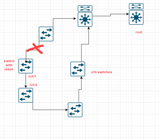
I have run a few debugs and this is what i’m receving.
```auto
Jan 11 2022 22:01:48.364 UTC: RSTP(150): Gi1/1 is now designated
Jan 11 2022 22:01:48.364 UTC: Found no corresponding dummy port for instance 150, port_id 128.1
Jan 11 2022 22:01:48.364 UTC: RSTP(210): Gi1/1 rcvd info expired
Jan 11 2022 22:01:48.364 UTC: RSTP(210): updt roles, information on root port Gi1/1 expired
Jan 11 2022 22:01:48.364 UTC: RSTP(210): we become the root bridge
Jan 11 2022 22:01:48.364 UTC: RSTP(210): Gi1/1 is now designated
Jan 11 2022 22:01:48.364 UTC: Found no corresponding dummy port for instance 210, port_id 128.1
Jan 11 2022 22:01:48.364 UTC: RSTP(303): Gi1/1 rcvd info expired
Jan 11 2022 22:01:48.364 UTC: RSTP(303): updt roles, information on root port Gi1/1 expired
Jan 11 2022 22:01:48.364 UTC: RSTP(303): we become the root bridge
Jan 11 2022 22:01:48.364 UTC: RSTP(303): Gi1/1 is now designated
Jan 11 2022 22:01:48.364 UTC: Found no corresponding dummy port for instance 303, port_id 128.1
Jan 11 2022 22:01:48.364 UTC: Found no corresponding dummy port for instance 303, port_id 128.9
Jan 11 2022 22:01:48.364 UTC: Found no corresponding dummy port for instance 303, port_id 128.9
Jan 11 2022 22:01:48.364 UTC: RSTP(303): Gi1/9 not in sync
Jan 11 2022 22:01:48.385 UTC: RSTP(150): updt roles, received superior bpdu on Gi1/1
Jan 11 2022 22:01:48.385 UTC: RSTP(150): Gi1/1 is now root port
Jan 11 2022 22:01:48.385 UTC: Found no corresponding dummy port for instance 150, port_id 128.1
Jan 11 2022 22:01:48.385 UTC: STP[150]: Generating TC trap for port GigabitEthernet1/1
Jan 11 2022 22:01:48.385 UTC: RSTP(210): updt roles, received superior bpdu on Gi1/1
Jan 11 2022 22:01:48.385 UTC: RSTP(210): Gi1/1 is now root port
Jan 11 2022 22:01:48.385 UTC: Found no corresponding dummy port for instance 210, port_id 128.1
Jan 11 2022 22:01:48.385 UTC: STP[210]: Generating TC trap for port GigabitEthernet1/1
Jan 11 2022 22:01:48.385 UTC: RSTP(303): updt roles, received superior bpdu on Gi1/1
```
and on the otherside i see similar, and disputes.
```auto
033478: Jan 11 12:04:19.464: RSTP(500): transmitting a proposal on Gi1/2
033479: Jan 11 12:04:19.474: RSTP(500): received an agreement on Gi1/2
033480: Jan 11 12:04:19.474: Found no corresponding dummy port for instance 500, port_id 128.2
033481: Jan 11 12:04:19.474: RSTP[500]: Gi1/2 dispute resolved
033482: Jan 11 12:04:19.995: RSTP(150): Gi1/2 Dispute!
033483: Jan 11 12:04:19.995: Found no corresponding dummy port for instance 150, port_id 128.2
033484: Jan 11 12:04:20.072: RSTP(210): transmitting a proposal on Gi1/2
033485: Jan 11 12:04:20.075: RSTP(210): received an agreement on Gi1/2
033486: Jan 11 12:04:20.075: Found no corresponding dummy port for instance 210, port_id 128.2
033487: Jan 11 12:04:20.075: RSTP[210]: Gi1/2 dispute resolved
033488: Jan 11 12:04:21.470: RSTP(500): Gi1/2 Dispute!
033489: Jan 11 12:04:21.470: Found no corresponding dummy port for instance 500, port_id 128.2
033490: Jan 11 12:04:21.501: RSTP(603): Gi1/2 Dispute!
033491: Jan 11 12:04:21.501: Found no corresponding dummy port for instance 603, port_id 128.2
033492: Jan 11 12:04:21.505: RSTP(603): transmitting a proposal on Gi1/2
033493: Jan 11 12:04:21.512: RSTP(603): received an agreement on Gi1/2
033494: Jan 11 12:04:21.512: Found no corresponding dummy port for instance 603, port_id 128.2
033495: Jan 11 12:04:21.512: RSTP[603]: Gi1/2 dispute resolved
033496: Jan 11 12:04:21.998: RSTP(150): transmitting a proposal on Gi1/2
033497: Jan 11 12:04:22.001: RSTP(150): received an agreement on Gi1/2
033498: Jan 11 12:04:22.001: Found no corresponding dummy port for instance 150, port_id 128.2
033499: Jan 11 12:04:22.001: RSTP[150]: Gi1/2 dispute resolved
033500: Jan 11 12:04:22.078: RSTP(210): Gi1/2 Dispute!
033501: Jan 11 12:04:22.078: Found no corresponding dummy port for instance 210, port_id 128.2
033502: Jan 11 12:04:22.078: RSTP(210): transmitting a proposal on Gi1/2
033503: Jan 11 12:04:22.092: RSTP(210): received an agreement on Gi1/2
033504: Jan 11 12:04:22.092: Found no corresponding dummy port for instance 210, port_id 128.2
033505: Jan 11 12:04:22.096: RSTP[210]: Gi1/2 dispute resolved
```
Is anyone able to shed any light on what could be causing this.
When the ring is in tact, spanning tree converges normally and everything is how it would be expected in terms of root bridges etc.
[Next page](https://forum.networklessons.com/t/rapid-spanning-tree-configuration/1139.md?page=2)