Hello Giovanni
I’ve created the following diagram to help us out:
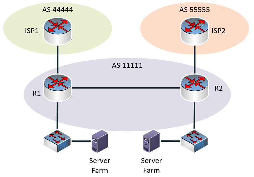
So you’re saying that the server farms at each site are on the same subnet, correct? Well, there are indeed several ways you can achieve this. Since the two remote offices have iBGP peerings between the routers, this means that they have some sort of WAN between them, that is independent of the ISPs themselves. Without knowing more about the type of WAN, here are a few thoughts:
- Create a L2 connection between the two sites, and span the server VLAN across the link, allowing the servers to be in the same VLAN. You could then advertise this subnet out of one or the other or both R1 routers to the Internet. This would require some changes in the WAN and internal topology of the network.
- If the WAN only functions at layer 3, then use a tunneling protocol such as L2TPv3 to tunnel layer 2 over a layer 3 link. This would allow the server farm VLAN to span the two sites. You could then advertise the subnet out of the two ISPs as you see fit.
- The use of Cisco’s Overlay Transport Virtualization (OTV) technology will allow you to have the same subnet at remote locations, while still maintaining the benefit of having dual redundant ISP connections that can be leveraged by both sites. This is done by allowing R1 and R2 to use first hop redundancy protocols such as HSRP and VRRP across the WAN. You can findout more about this at the following post:
Now notice that all of the options simply speak about the necessary topology to allow for the spanning of the VLAN across the WAN. The mechanism of then advertising these prefixes to both ISPs is the same in all cases. All that is necessary is to make that VLAN/subnet accessible on some interface on both R1 and R2, so that it can then be advertised however you see fit to the ISPs using eBGP peerings.
I hope this has been helpful!
Laz