VXLAN would also be a solution in this case, absolutely. You could tunnel your Layer 2 topology over the Layer 3 underlay network and get the same result. If you have a large enough network, it would definitely be more elegant than L2TPv3.
OTV differs from VXLANs in purpose. VXLANs allow you to extend your Layer 2 topology, essentially your VLANs, by tunnelling them over a Layer 3 network. This adds flexibility, ease of deployment, as well as a much larger number of manageable VLANs, which is especially useful for ISPs and datacenter providers.
OTV on the other hand is used to allow for the spanning of Layer 2 topologies across disparate and remote datacenters while at the same time, preventing the waste of precious bandwidth across the WAN, something that VXLANs are not designed to do.
This is a very simplistic view of OTV however, as it is much more involved than this, but for the purposes of this discussion, these are the primary differences, as far as this specific application is concerned.
Yes, let me clarify. My meaning is that we are assuming that we are creating some sort of peering between the CE and ISP routers. Now this can be eBGP, it may also be iBGP, it depends on the arrangement you have with your ISPs. In any case, internal CE routers will most often have an iBGP peering, but also will be routable via their IGP internal to the enterprise network.
Because inbound traffic is essentially sent to you, you do not have the ultimate control of how traffic enters your AS. Your ISPs may have outbound policies that will always override all of your attempts to influence inbound traffic. However, you do have the option of influencing inbound traffic. There are several ways to do this including:
Leaking more specific routes - BGP will prefer more specific routes than summarizations, but some ISPs may consider this to be a “hostile” act, as it causes BGP tables to increase in size.
All of the above are implemented on the customer side of the connection, because this is the side that you have control over. Remember however, that the ISP has the final word for inbound traffic. For this reason, make sure to discuss your requirements with the ISP before actually implementing any of these. ISPs will usually be more than happy to accommodate your needs, and will provide you with suggested solutions to what you need. To find out more about examples or implementations of these, click on the links in the above list to see the associated lessons.
Many thanks for the detailed explanation. One question remains unanswered. What kind of attributes we can choose to manipulate outbound traffic ? Local preference ? or any thing else ?
Outgoing traffic is what you have complete control over, so you can use any of the attributes that can directly be manipulated. The most commonly used, and easiest to deploy are weight and local preference. Because these are the first to be examined when selecting a BGP path, any changes to these will take precedence over any other attributes that may affect routing.
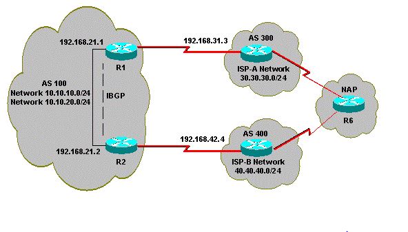
Hi , I have uploaded a multiohomed network with multiple routers involving two different ISP. I am trying to achive load sharing here . However my requirements are as below.
1.AS 100 accepts the local routes from both providers, along with a default for the rest of the Internet routes.
The outbound traffic policy is:
1.Traffic that is destined to AS 300 goes through the R1-ISP(A) link.
2.Traffic that is destined to AS 400 goes through the R2-ISP(B) link.
3.All other traffic should prefer default route 0.0.0.0 through the R1-ISP(A) link.
4.If the R1-ISP(A) link fails, all traffic should go through the R2-ISP(B) link.
The inbound traffic policy is:
1.Traffic that is destined for network 10.10.10.0/24 from the Internet should come from the ISP(A)-R1 link.
2.Traffic that is destined for network 10.10.20.0/24 from the Internet should come from the ISP(B)-R2 link.
3.If one ISP fails, the other ISP should route traffic back to AS 100 from the Internet for all the networks
Please note the above is taken from cisco website . They have given configurations for the same but I could not get the whole of it. Could you please explain it how well can we achieve the requirements mentioned above ?
Remember that you have full control over traffic that is sent from your AS to other AS’es. You don’t have ultimate control over incoming traffic, however, you can influence it in various ways. For influencing incoming traffic, take a look at this post:
If you do want to adjust incoming traffic, before you inject any BGP attributes into your ISP’s AS’es, have a chat with them and tell them what you want to do. They are often very accommodating in such cases.
Now specifically, for your outbound traffic policy, numbers 1 and 2 will happen automatically simply because of BGP routing. Number 3 can be configured most simply by adjusting the Weight Attribute. You can also adjust other attributes to achieve this. For a link failure (number 4) BGP will (eventually) reconverge, but you may want to use Next Hop Tracking and Additinoal Paths BGP features to speed up convergence.
For inbound, as mentioned before, talk first with your ISPs. It may be that they will do all the routing for you. They may ask you to configure some things on your end as well. The attributes involved in this are those described in the shared post above.
I’m trying to create a network which connects to the Internet as indicated in the image below.
I have a single multihome setup with each router also connected to multilayer switches. I’d like the routers to load-balance by setting two default routes: one to the ISP and one to the other router.
There are several issues to be dealt with here and several solutions for them. These include:
Connectivity of Routers to the ISPs - This is achieved using BGP. Typically, you have a BGP AS on your own routers, and then each ISP provides you with an AS of its own, and you create eBGP peerings. You can then adjust your BGP Attributes and parameters in the routers so that if connectivity is lost, one router will take over from the other.
Connectivity between routers and internal MLS’es - Here you can either use a first-hop redundancy protocol (FHRP) such as HSRP in order to allow the MLS’es to reach either router. Typically however, in such a situation, you would use some for of equal cost or unequal cost routing so that you can direct traffic to whichever edge router you want. This way, if a router is lost, routing protocols will dynamically detect this and send traffic in the appropriate direction.
Connectivity between MLS’es and internal network - Here in most cases you will use an FHRP such as HSRP so that internal devices will have a redundant gateway. If one of the switches fails, internal hosts will not lose connectivity, but will continue to have access using the other switch as the gateway.
In all three cases, avoiding loops on the routers simply involves employing routing protocols and configurations appropriately.
Hi Rene,
In the example of dual homed (connected to a single ISP router using dual links), one way to load share is by configuring loopbacks on both routers, configure reachability between the loopbacks (via static route or IGP) and use update-source, ebgp multi-hop 2, commands to get the BGP up and load share across the 2 links.
Is there another way? like configure 2 neighbor statements to the same ISP router and use maximum-paths 2?
Actually, it is possible to create two BGP neighor adjacencies between the routers over different physical links, and load balancing will take place using the maximum-paths option. Under normal operation, this would work fine, however, in the event of a topology change, it would take some time for reconvergence to take place. With the first scenario you described, redundancy would be achieved instantaneously.
For reference, the first scenario you described can be found in detail in the second half of the following lesson:
Configurations that allow load balancing/sharing via BGP can be found in the following two lessons:
HI
I have an usual situation,
current set up is Nexus core 1 and 2 in a data centre running OSPF and connected to ISP1 via BGP all good so far
Now we have a new connection via a firewall to our new ISP running BGP
The problem I am having is the communication between 2 WAN sites that have the different ISP, they have connection problems to each other, because the core routes out via ISP1 because OSPF is the preferred protocol, but it comes back via the ISP 2.
AS the is OSPF are 0 I am wary about redistruting the OSPF into the BGP peer that is facing ISP 2
whats the best way?
I’m having a little trouble understanding your topology. It would be helpful if you shared a diagram with us that shows both your remote (WAN) sites, as well as the datacenter core routers, firewall and ISP1 and ISP2 routers.
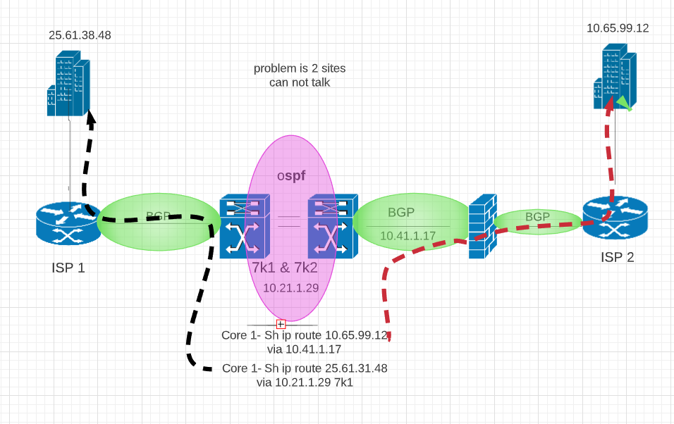
The Nexus 7k are in a pair running OSPF per interface between them. Currently we have 80 remote sites connected to ISP 1 only. We connected second 7k to a Fortinet Firewall and then to second ISP 2 and 1 site was added 10.65.99.12. This site has full access and functionality which we want
All are other sites are connected to ISP 1 and they to all work fine. The problem is when these 2 sites try to talk to each other, they cant. The ISPS’s are not in HSRP so they do not talk to each other. If I do a sh ip route to 10.65.99.12 it correctly goes via second ISP, If i do the same for 25.61.31.48 it goes via core 1 which is connected to ISP 1. So they dont connect
The BGP config is standard
There are a couple of things that come to mind here. First of all, you have a site via ISP1 that is reached at 25.61.38.48 (let’s call it site 1) which is a public address. On the other hand, we have another site (site 2) connected via ISP2 with an address of 10.65.99.12, which is a private address. I’m assuming this site is connected with some kind of VPN to the firewall, and thus all connectivity between your nexus switches and this site actually occurs over private IP addresses and doesn’t touch the public Internet. One question I do have is how does site 2 reach the internet? Because when site 2 wants to communicate with 25.61.38.48, it will go via the internet connection, and not via the OSPF area of the nexus switches.
This is because on all routers, the default administrative distance for eBGP routes is 20 while for OSPF it is 110. This means eBGP routes will be preferred, so communication between the two sites will attempt to take place over the internet at large, and not over the nexus switches.
But site 2 can only be reached via the nexus switches, due to the fact that it is connected via a VPN, so any such communication fails.
One solution may be to change the administrative distance only for those routes for which you want to prefer OSPF rather than eBGP, but this must be done carefully, as you do not want to become a transit network for general internet traffic.
I hope this helps you out in your troubleshooting efforts!
Lapapides
The 25 subnet is actually a private address! So no VPN to ISP firewal and no nat
its simply one subnet 10.65.99 from ISP 2 can not reach 25 subnet that goes out via ISP 1
There could be a number of things that are causing this behaviour. The first thing that comes to mind is that the 25.61.38.48 address is actually a public address, even if you are using it internally. Now when you are communicating from one site to the other, depending upon where along that path the packet reaches the network of ISP1 or ISP2, the routing found within the ISPs may route that traffic to the real destination with that address. Best practice dictates that you use RFC1918 IPv4 addresses internally to avoid such routing problems. Any BGP configuration of the ISP will prefer to send such addresses to the Internet rather than to the internal network, since eBGP has a higher priority (lower AD) than any IGP.
For me it is still not clear how the remote sites are communicating with the two Nexus 7K devices. If the connection to these devices is over an ISP, and they are using private addresses, how are you getting to those sites if not with a VPN? Can you further clarify your topology?
Regardless of this, it may be that you will simply have to examine routing along the whole path of the communication. Examine how each device along the path routes traffic between these two sites, and find out where the packets are being dropped. Once you know where, then you can further troubleshoot to determine why they are being dropped.
It’s still not clear to me what you want to achieve. I understand that you don’t have communication between the two network subnets/segments that you mentioned, and that the issue does look like it has to do with routing, but in order to get deeper into the reasons for this failure, it will take active troubleshooting along the routed path to determine where the packets are being dropped. Let us know some of your results of this troubleshooting so that we can further help you in resolving the problem.