Spanning Tree Port States

Hlw Rene,

Root Port , Designated port will send & Receive BPDU right ??

Alternate Port will send and receive BPDU ???

How a Alternate port know , It have to move Listening, Learning , Forwording after Root port down as per attached Topology on switchC.

br/
zaman

Mohammad,
The concept of an Alternate port was introduced with Rapid Spanning Tree. This feature takes over what the traditional (802.1 D) spanning-tree enhancement of “uplink-fast” used to do. The Alternate port serves as a “hot-standby” for a switch’s Root Port, but Alternate Port is considered to be in a Discarding state (Discarding is the RSTP term for Blocking, Listening, and Disabled for spanning-tree).

This means that an Alternate port can receive BPDUs but will not send them. As soon as a Root Port fails, the Alternate Port will immediately transition to forwarding, skipping the Learning state (there is no such thing as “Listening” in Rapid Spanning Tree).

You are correct that Root and Designated ports both send and receive BPDUs.

1 Like

OMG,This is the easiest way to understand the stp concept and ports state.

1 Like

Hi Rene,

q1) What is the difference between a port in BLOCK and LISTEN state ? LISTEN does send and receive but BLOCK only receives BPDUs ?

q2) I saw an amber light on a port in BLOCK state, but if we have PVST and we configure different root bridges, how does the switch
reflect a ND port that is BLOCK in 1 VLAN but not BLOCK in another VLAN ?

q3) “Only a root or designated port will move to the listening state”
what is the state for the interfaces/ports before everything (e.g. root bridge, root port, designated port) are determined ? – still listening ?

Regards,
Alan

Hi Alan,

  1. In the blocking state, the switch only receives BPDUs but does not send them. In the listening state, we send and receive BPDUs.
  2. If it's an access interface then it will be amber. Trunk interfaces will always have a green led (since you can have more than one VLAN).
  3. When you first enable the interface, it will start in the listening state.

Rene

Hello Rene

In your post you mentioned ports in block mode take the 20+15+15 before forwarding in some cases. Could you tell me in which case cause i was trying to simulate but i only got lis->lear->for states and not Max age time.

Thanks in advance.
Jose

Hello Jose

There are two situations which require a switch to begin STP convergence procedures. The direct and indirect link failures. Let’s take a look at both:

  1. A direct link failure is when a switch detects a loss of carrier on its own port and immediately declares the port as disconnected. Take a look at the following figure:

image

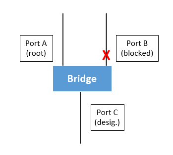
The STP is converged and Port B is in blocking state. Imagine Port A goes down. The bridge no longer detects a carrier on that port and immediately causes Port B to go through the STP procedure going into the Listening and Learning states for a total of 15+15=30 seconds. Convergence time in this case is at 30 seconds.

  1. An indirect link failure is when a link goes down on another switch. This is not immediately detected. Take a look at the following figure:

image

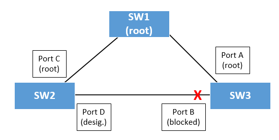
In this figure, SW1 is the Root Bridge and Port B on SW3 is the blocked port. Also, assume SW2 has a better Bridge ID than SW3. Imagine that Port C on SW2 goes down. How will Port B on SW3 react? Let’s go through the steps.

  • SW2 will no longer be receiving BPDUs from SW1 and will declare itself root bridge.
  • SW2 will start advertising new BPDUs to SW3 telling SW3 that it is root bridge. SW3 will ignore them because SW1 BPDUs it’s still receiving are superior.
  • SW3 will keep the information from the previously received BPDUs on Port B for 20 seconds which is the blocking timer
  • Once this timer is expired, Port B will begin considering the BPDUs in the Listening state and will begin relaying SW1’s BPDUs to SW2 since they are superior
  • Then SW2 will detect the better information it is receiving on Port D and will cycle the port through Listening and Learning.
  • Both switches (2 and 3) will eventually place their ports in the forwarding states and connectivity will be recovered.

In this case, the total time is 20+15+15=50.

The 50 second convergence time is more often quoted for STP because it is the absolute longest time that you may have to wait for STP to fully converge.

I hope this has been helpful!

Laz

2 Likes

Thanks so much Laz.

Jose

1 Like

Hi Rene and staff,
you can tune spanning-tree timers (delays)

  • forward timer between 4 and 30s (15s by default) used as listening delay and learning delay
  • hello time between 1 and 10 s (2s by default)
  • max age between 6 and 40 s (20 s by default)

In blocking mode you have to wait 20 s to forward to listening state: I did not find how to tune this delay

Is it that the blocking delay is equal to max age: this would be logic
Please could you confirm ?
Regards

Hi Rene and staff,
reading carefully the last Laz’s post (in the case of indirect failure), i should have done it before my previous post (i apologize)

it seems that the delay in blocking mode is not 20s, but result from the formula

blocking delay = max age - BPDU age
(with max age = 20s by default)

BPDU age starts at 0 from the root, and is incremented by 1 on each downstream SW

So, max age = 20s by default (and you can tune it between 6 and 40), but you cant tune blocking delay because it results from the formula

Yet, this is why Laz says the absolute longest time is 50 s, because the absolute longest time is 20s for the blocking mode
Please could you confirm ?
Regards

Hello Dominique

Yes, tuning the max-age will indeed tune the blocking delay… so what you describe in your post is correct.

I found the following document useful to further understand the intricacies of STP timers, I hope you find it useful.

I hope this has been helpful!

Laz

Hi Rene,

The port which is in blocking state has to wait for 20 seconds , any specific region behind this ?

Hello Pradyumna

The blocking state timer (and all STP timers) are configured in such a way so that the formation of a layer 2 loop can be avoided.

In the lesson, Rene states:

When an interface is in blocking mode and the topology changes, it’s possible that an interface that is currently in blocking mode has to move to the forwarding state. When this is the case, the blocking mode will last for 20 seconds before it moves to the listening state.

As soon as a blocked port receives information that the topology is changed, via BDPUs (a blocked port will only receive and process BPDUs), and it too may need to change, it doesn’t immediately go into the listening state but waits 20 seconds. This delay is used to allow the other areas of the STP topology to stabilize before changing to the listening state, and reacting to them.

The timers (blocking 20, listening 15, learning 15) have been defined after experimentation and research, and are based on the optimum values for most network topologies. Remember, that for this lesson, Rene is speaking about the original STP implementation of IEEE 802.1D defined in 1990 (thirty years ago!!), an implementation that is great for teaching network fundamentals, but one that should not be used in modern networks.

I hope this has been helpful!

Laz

1 Like

Q-1:- What i understood, kindly correct me if i am wrong .
If a root and designated port breaks then the switch will take only 30sec to make the block port as root port …
But when it take 50 sec.?

How TCN and Configuration BPDU transited between the switches ??
(SW1=>sw2=>Sw3)
Will sw1 will send the BPDU to sw3 ?, if it will send then what sw-2 will modify in that bpdu before it sends to sw3 ?..

Hello Narad

If a port is down, and it is just plugged in, then it will take 50 seconds because it goes blocked for 20, listen for 15, and learning for 15 = 50 seconds. Even if there is a topology change, such as when a root or designated port fails, any ports that were in the blocking state will remain in that state for 20 seconds before going to listening and learning. Therefore the total amount of time would still remain 50 seconds before forwarding…

Take a look at this lesson:

I hope this has been helpful!

Laz

Thanks Sir for your help…!!

1 Like

Hi,

regarding case 2, which are previously received BPDUs received on port B of switch 3 from switch 2? What makes them superior BPDUs?

Hello Quirik

Switch ports in the blocking or alternate state still receive BPDUs from the connected switch. So for the following statement here is the explanation:

So before port C on SW2 went down, when STP was converged and stable, port B had received some BPDUs from SW2. These are the “previously received BPDUs.” When the topology changed, SW2 sent new BPDUs with new information, stating that it is the root bridge. SW3 does not process these yet, until the blocking timer expires.

What makes the superior? I assume you are referring to this statement:

The statement says that once the blocking timer expires, the newly received BPDUs are considered. However, they are not accepted because those received from SW1 are superior to those received from SW2. So, SW1 becomes the root once again, as it should be.

Does that make sense?

I hope this has been helpful!

Laz

1 Like

Hello,

I have tried htese topology changes in a lab environment , For a designated port here is the cases and results:

  1. When I connected a server to a designated port, it goes directly to Forwarding , I didnt see any TCN notification from debug. Why is that? (There is no portfast conf.)
  2. When I shut and no shut the designated interface , It acted accordingly, it goes 15 sec listening, 15 sec learning and then forwarding, this is ok,

For an Alternate port.

  1. When I shut and no shut the interface, It first go listening but after 2 sec it went directly to Blocking, Does it because it uses pvst and not classic 802.1d?

Also

I saw something like this in another resource:

In STP, regardless of their own configurations, all other switches inherit the timer configurations of the root bridge. This is because the root bridge uses Bridge Protocol Data Units (BPDUs) to disseminate its timer values throughout the network.

But When I tried this in my own lab, I change a non-root bridge ID timers, and I waited a little bit, but it didnt sync itself according to root bridge Timers, I even tried to triggered the sync by changing timers on root briddge but it didnt work,

Why is that?

Thanks

Hello Görgen

This is expected behavior. Keep in mind how a topology change is defined. When you connect a server to a designated port, the switch doesn’t see this as a topology change, hence no TCN is sent. When you shut and no shut the designated interface, the switch goes through the STP states (Listening, Learning, Forwarding) as expected. This is because the interface was manually shut down and brought back up.

Yes, PVST+ skips the learning state and goes directly to blocking.

Hmm, I’m curious to know where this information was published. STP does not typically synchronize timers across all switches in the network. In both the original STP and its subsequent versions like RSTP and MSTP, timer synchronization is not a feature.

In STP, the root bridge sends out BPDUs which contain information about the network topology, the root bridge ID, and the root path cost, along with the timer values like Hello Time, Max Age, and Forward Delay. However, these timer values are not meant to synchronize the timers of all switches in the network. Instead, they are used by each switch to understand the network topology and to time their own STP state transitions.

Each switch in the network will use the timer values from the root bridge’s BPDUs for STP calculations, but they maintain their own timers and do not automatically adjust their local timer settings to match those of the root bridge.

I hope this has been helpful!

Laz