Spanning Tree Topology Change Notification (TCN)

Hi All,
Everybody talks about a link breaking down when it comes to Topology Change. Can i know what exactly happens when a new switch is added to current STP topology.

  1. What would be the first state of new switch port and how it works?(I know it starts from blocking state, I want to know the series of events that happens between those two ports - old and the new one)
  2. I am pretty sure that TCN message won’t be sent to root by adjacent switch because nothing to be erased from MAC Addr table(whole purpose of TCN message). Please confirm my understanding on this!
  3. will there be a RB election process again?

Thanks for your reply in advance!
I will also work it out in my lab by enabling “debug spanning-tree events” command.

1 Like

Hello Pradeep

For the following, we assume that we are using simple STP (802.1D). If you have a stable topology where STP has converged, and you add a new switch to one of the switchports of the switches already in the topology, then the following would happen:

  1. The new switch considers itself the root bridge. The port on which it is connected to the other switch will begin briefly in the blocked state as you mentioned.
  2. Next, that port will transition to the Listening state. During the listening state, BPDUs are exchanged. Note that both ports on both ends of the link will be transitioning from state to state at the same time assuming the timers are the same, so both ends will be in the Listening state as they exchange BPDUs. During the BPDU exchange, the new switch will learn if it is indeed the root bridge or if the current root bridge will remain, depending on the priority values and the MAC address.
  • If the new switch is not the root bridge, its port will assume a role of root port while the interface at the other end of the link will assume a role of designated. (assuming no L2 loop is created with the new switch).
  • if the new switch is the root bridge, the port becomes designated and superior BPDUs are sent on the link which will cause the rest of the switches to re-converge their STP orientation.
    The ports continue to transition until the topology converges.

The conditions under which a TCN is sent are very specific and they are stated in detail by Cisco. Cisco states:

A bridge has detected a topology change:

  • When a port that was forwarding is going down (blocking for instance).
  • When a port transitions to forwarding and the bridge has a designated port. (This means that the bridge is not standalone.)

Once a topology change has been confirmed, a TCN will be sent.

The process to send a notification to all bridges in the network involves two steps:

  • The bridge notifies the root bridge of the spanning tree.
  • The root bridge “broadcasts” the information into the whole network.

It is only under those circumstances that a TCN is sent. It does not specify that a TCN is sent only if there are actual MAC addresses in the MAC address table of the new switch that is being connected. It doesn’t take this into account. A TCN will be sent and the aging time will be reduced regardless of whether or not there are actually new MAC addresses to be learned.

Yes there will be. As stated at the beginning, BPDUs will be exchanged and if the priority and MAC address of the new switch are indeed superior, then yes, an election and a subsequent STP reconvergence will take place.

I hope this has been helpful!

Laz

2 Likes

Hi Rene,

One question. What’s the point of clearing the ARP cache (default timeout 300s) on a TCN? Once an address expires, don’t you just fetch it from the ARP table again (timeout 4hours)? Or do the 15 second timers apply to both the ARP cache and table?

I am guessing that there is no ARP even if the 15 seconds duration expires since the ARP timeout is 4 hours.

Any clarification here would be helpful.

Thanks!

1 Like

Hello Seyed

When a TCN is recieved, it’s not the ARP table that is cleared, but the MAC address table. The ARP table remains intact. The purpose of clearing the MAC table is that MACs of devices not directly connect to a particular switch may appear to be associated with an incorrect port on that switch if a topology change takes place. If this is the case, you have to wait 300 seconds for the MAC address entry to expire before that particular MAC address is correctly updated in the table of that particular switch. The result is having STP reconverge in several seconds, but having to wait up to 300 seconds for the correct MAC address table entries to converge.

I hope this has been helpful!

Laz

Hi,
my question is when the switches set the mac address table aging time to 15 seconds?
when they receive a TCN from any switch? When they receive a TCA from root bridge or when they receive a TC from the root bridge?
Thanks in advance.

Hello Ignacio

According to this Cisco documentation, aging time is reduced to 15 seconds by switches when they recieve the TC from the root bridge.

I hope this has been helpful!

Laz

Thanks Laz,

sorry for late reply from my side. what you have explained is perfect and my professor also told the same. Even i told the same answer in one of my interview as well!

Thank you
Pradeep

Hello Pradeep

Great to hear that I was of help! Always here for anything else you need.

Laz

Hi Rene,
Based on your explanation and examples a TCN is generated any time a port goes up and down. In the case of a link that goes down between two non-root switches, which one of the switches will generate the TCN toward the root bridge or will both?

1 Like

Hello Vaughan

According to Cisco, in the original STP specification, a TCN will be generated:

  • When a port that was forwarding is going down (blocking for instance).
  • When a port transitions to forwarding and the bridge has a designated port. (This means that the bridge is not standalone.)

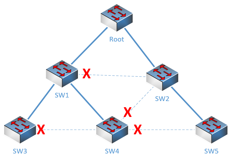
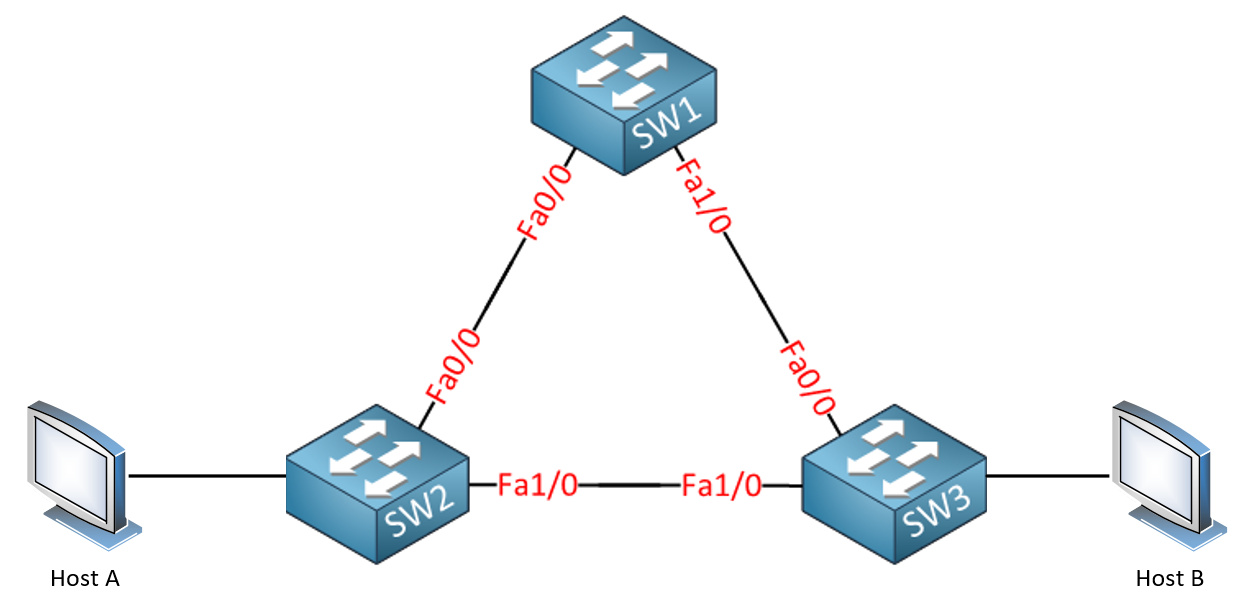
Now there are two scenarios. Let’s look at this topology, where all switches are interconnected as shown and the red X’s show which ports are blocked by STP:

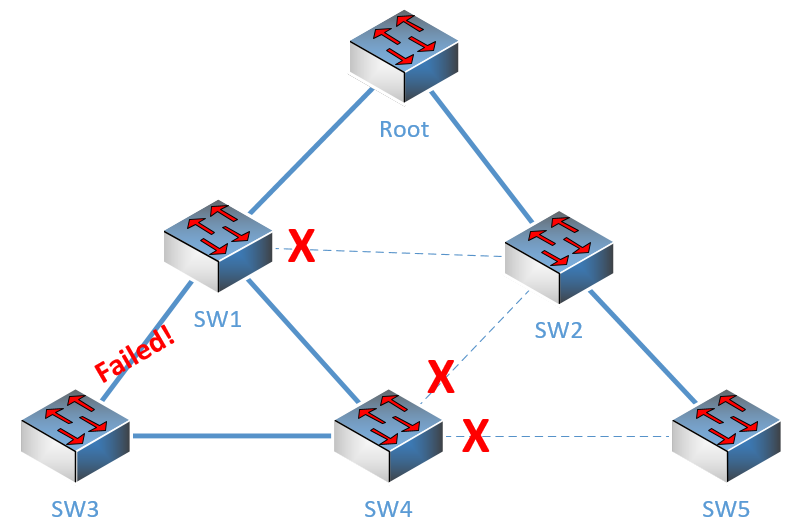
Now if the link between SW1 and SW3 goes down, SW1 will send a TCN because one of its ports went down. SW3 will not be able to send a TCN, since the port that went down was the port through which it had connectivity to the root bridge (and to the network itself). SW3 has thus lost connectivity, at least until STP reconverges. So in this scenario, only SW1 will send the TCN and not SW3. However, when STP reconverges, we get the following new topology:

In this case, a port on SW3 (that connects to SW4) has transitioned from blocking to the forwarding state and thus a TCN will be sent via that interface to SW4 and onward to the Root. Note however, that the port of SW4 connected to SW3 has not changed states, thus SW4 will not send a TCN.

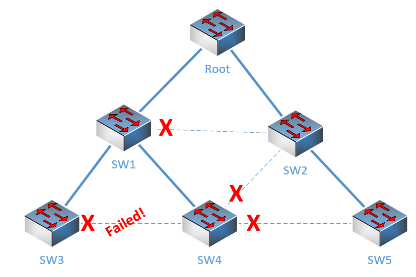
Now for the second scenario, let’s go back to the original STP topology and imagine this time that the link between SW3 and SW4 has failed. Remember, SW3 had this port blocked:

In this case, only SW4 will send the TCN. This is because SW3 had its port in the blocking state and it has changed to the down state. By definition, TCNs are not generated in such a case. However, the port of SW4 was in a forwarding state, even though its counterpart on SW3 was blocked. This transitioned to the down state, and thus SW4 will generate a TCN.

A link that has one end blocked by STP will have the other end in a forwarding state. So if the link goes down, that port will have moved from a forwarding state to a down state, which would generate a TCN.

I hope this has been helpful!

Laz

1 Like

Hi Rene and staff,
thanks a lot to Laz for his last post which is a very good clarification when TCN is generated or not
Now, i would like to be clear with BPDU format
The BPDU format use the columns type and flag to handle the different types of BPDU

First with the column “type” you can distinguish configuration BPDU (with type 0x00) and TCN BPDU (with type 0x80)
BPDU TCN is a BPDU with type 0x80 and padding for the following columns

Then the TC BPDU (send by root bridge) is a special configuration BPDU (type 0x00) with flag LSB (that what i read). I dont know what LSB means: could you tell me ? In this case, one bit of TC BPDU flag (1 byte) is set to1: is it the bit 2^8 or the bit 2^0 ?

Then we have the BPDU TCA: this not a config BPDU, neither a TCN; just an acknowledgement of TCN to stop transmission of TCN (each hello time=2s) by the downstream SW to the upstream SW.
So what is the type of BPDU TCA ? i read MSB is the flag for BPDU TCA (i dont know what MSB means)
Could you clarify ?
Regards

Hello Dominique

Yes, the type field is used to determine if a BPDU is a configuration BPDU or a TCN BPDU. If it is a configuration BPDU, it will have a value of 0 and if it is a TCN, it will have a value of 0x80 (or 128 in decimal).

The flags field of a BPDU frame is made of eight bits or one byte. If the Least Significant Bit (LSB) of that byte is set to 1, then this indicates that the BPDU is a Topology Change (TC) BPDU. If the Most Significant Bit (MSB) of that byte is set to 1 then the BPDU is a Topology Change Acknowledgement (TCA), which is a response.

A BPDU TCA is considered a control BPDU.

I hope this has been helpful!

Laz

Simple question with an equally simple answer I am sure:
When a non-root switch port transitions from blocking to forwarding a TCN will be generated so that all switches will know of the change and can readjust as necessary to prevent data loops. This TCN, I believe, is sent out the root port as that is the quickest route to the root bridge. Along the way other non-root switches could receive this TCN before it reaches the root bridge. For these intermediate switches: do they change their MAC address table timeout from 300 secs to 15 secs as they receive this TCN from the downstream switch or do they wait until the root switch issues the “authorization” TCN?

Hello Brad

Switches will reduce their MAC address table time out to 15 seconds only when they receive the broadcasted TC BPDU that comes from the root bridge and not when they receive a TCN that is on its way to the root bridge. The specific event that triggers the change of the MAC address table timeout in all routers is the TC bit set to 1 in the BPDU. Take a look at the following diagram.

image

This shows the structure of the BPDU and the flags that it contains. Regardless of whether you are using 802.1d (standard STP) or 802.1w (RSTP), the TC bit is the same. Note here that a TCN has all flags set to 0. Actually, a TCN is a very simple BPDU that contains absolutely no information. It is just characterized by the fact that it is the only BPDU that is sent towards the root bridge.

So the MAC address table ageing timer is reduced to 15 seconds only when the TC BPDU is received from the root bridge and not when a switch receives a TCN from a downstream switch.

I hope this has been helpful!

Laz

Quick question. When the TNC is sent to the root bridge and the Root bridge sents TC downstream. I get that this is received on all ports even ones that are blocking. How does that not create a loop itself since it’s in an ethernet frame? or does the Spanning tree converge fast enough that that doesn’t become an issue?

Thank you,

Cedric K.

Hello Cedric

A layer 2 loop will occur when the destination MAC address, which may exist in the MAC address table of multiple switches, causes switches to forward frames out of multiple ports. Take a look at this topology:


Let’s assume that STP is not running. If host A sends a frame to host B, then SW2 will receive the frame, will see that it does not have an entry for the destination MAC, and will send it out of all of its ports. Both SW1 and SW3 will receive the frame, and do the same. When the frame comes back to SW2 it will do the same again, and so on. Even if switches begin to populate their MAC address tables with the destination MAC, they will continually flap between exit ports. What causes the loop is the fact that the destination MAC has multiple physical paths to get to it, and this is something that causes switches to continually flood traffic, causing a loop.

In the case of a BPDU or a TC that is sent to blocking ports, the destination MAC address in this case is the switch itself. So the frame enters the switch and is not forwarded any further, thus no loop occurs.

I hope this has been helpful!

Laz

hi Rene
i wan ask about TCN send in listening state or in learning state

Hello Mohamed

A TCN will only be sent out of a root port in the event that there is some change in the topology. This is because TCNs are always sent upstream towards the root bridge. However, root port only be comes a root port once the STP network is converged. Therefore, a root port will never be in a listening or learning state.

I hope this has been helpful!

Laz

thank u lazaros
According to this article 6, switches in a spanning tree topology send TCNs out of their root port. In the scenario, SW1’s port fa0/14 is not a root port therefore it shouldn’t send a TCN out of that port.

Or is it the case that if a switch detects that it’s root port has gone down, it sends a TCN out of designated ports instead?

Which ports does send TCN inside the network? Only the Root Ports?

If one switch has his root port down, will it send TCN for his designated ports?

Thanks!