Spanning Tree Topology Change Notification (TCN)

Hello Sean

You make a very good point with your questions. If you have a situation where a single device will be receiving only one stream of UDP packets over an extended period of time, then yes, you would have a problem. And you are right, if this continued for over five minutes, the MAC address table entry would indeed expire, and the traffic would start being flooded. Having the MAC address table flushed continuously would simply make the problem even bigger.

The key here is in this statement:

The answer is yes. However, it is extremely rare that you would have a situation where a host will only receive data without sending a single frame over an extended period of time. Rene used the example of the backup, and you used the example of an IP camera, but these are two extreme examples that are highly unlikely but are used in order to describe the phenomenon.

In both of these situations, the backup device as well as the server receiving the IP camera feed will indeed have this unidirectional flow of data. However, these devices do have additional sessions that are taking place in which at least some frames will be sourced from them, allowing the switch to repopulate the MAC address table. If the phenomenon does take place, it will take place only for a few minutes.

In the unlikely event that you have such extreme cases, where a device simply receives data without sending any frames over an extended period of time, then the solution would be to enter a static MAC address table entry that never expires.

If we relied only on the multicast traffic, then you would be correct that after five minutes, the destination MAC of the receiving host would expire from the switch’s MAC address table, and would be flooded. HOwever, multicast uses IGMP to determine which hosts should receive which multicast streams. IGMP messages are periodically sent between multicast routers and multicast hosts, enabling a switch to renew the MAC address of the host in the MAC address table. Not only that, but IGMP snooping is a mechanism that continually updates the MAC address table with multicast MAC addresses which correspond to the ports where receivers are connected. So due to these mechanisms, the MAC address table is always up to date.

The bottom line is that over a period of five minutes, there is almost no chance that a network device will not send some frame so that the MAC address table can be updated. Over 15 seconds, however, this may be a problem and that’s where PortFast can help in this phenomenon…

I hope this has been helpful!

Laz
1 Like

Hi Laz,

I just want to confirm how uplink fast works with regards to TCNs in the above example.

For uplink fast, after the link between SW1 and SW3 fails, the SW3 and SW4 link will immediately transition to forwarding, at which point SW3 will start sending out dummy multicast frames on behalf of MAC addresses in its table.

So, even though at the same time the rest of the network is receiving instructions from SW1 to flush it’s MAC addresses for anything older than 15 seconds old, with uplink fast enabled, the switches will have their mac address tables corrected even more quickly and as a result reduce the chances of traffic being black holed, which could still happen during the 15 second window. Is my understanding correct?

Thanks,

Sam

Hello Samir

Yes, I believe your reasoning is correct.

Laz

1 Like

Hello Sir,
The more I read about STP Topology change the more I’m getting confuse. The link between SW1 and SW3 fails. SW1 loses its RP. So it assumes it has become the root and start sending BPDUs to SW2 on port F0/14 which already has a Superior BPDU. So SW2 will wait for the Max Age timer to expire then it can process the BPDU. SW2 also receive Config BPDU with TC flag bit on from the root SW3 on interface f0/19 which is in blocking state. So it will have to wait for the Max Age timer to expire then it can advertise the BPDU to SW1. SW2 transitions into listening state and compares the BPDUs on both interfaces F0/14 and F0/19. The superior BPDU from the root is also relayed to SW1 on interface f0/14. As it is a Superior BPDU the Port becomes the root. On SW2 the superior BPDU is received on the F0/19 interface which becomes the RP and F0/14 the DP. I think its a more logical explanation. As per your explanation even if SW1 sends TCN BPDU to SW2 on interface F0/14. SW2 will have to wait for the Superior BPDU on its root port to expire.

Hello Reetesh

Thanks for your response! The point of my post was to answer the specific question of whether or not TCNs are sent out the root ports or not. Your explanation looks good and is more comprehensive and covers the whole process in detail, much like in the lesson. Thanks for sharing that, it’s much appreciated!

Laz

1 Like

Hi, Rene! How are you?
You did a great job, but I have a doubt.

When a Root Bridge receives a TCN, it will change the BPDU Type and forward this BPDU to all its port, right? But what about a flag field?
The Root Bridge will change both BPDU Type and flag field at the same time?

Thanks!!!

Hello Marcus

Don’t think about the root bridge as “changing the BPDU type”. Think about it this way.

There are two types of BPDUs, TCNs and configuration BPDUs. When a topology change occurs on the network, the switch that detects it will send a TCN out of its root port. That TCN will be retransmitted by all bridges that receive it, via their root port. This ensures that the TCN will eventually reach the root bridge.

Once the root bridge receives the TCN, it will begin sending configuration BPDUs out of all of its ports. On those configuration BPDUs, the TC flag will indeed be set. More about the TC flag can be found here:

I hope this has been helpful!

Laz

1 Like

I have a few questions regarding the topology change process in spanning tree that I am having a hard time finding answers for, I am hoping someone can help me.

  1. When a switch in 802.1D receives a TCN BPDU from the RB, it is supposed to reduce its CAM table aging time from 300 sec to 15 sec. However, the RB will continue to send out the TCN BPDU for Max Age + FWD Delay (35 sec by default). If a switch ages out some CAM entries after 15 seconds, then technically it could still continue to receive TCN BPDU’s after it already flushed the entries. Will the switch only flush once? Or will it flush again because its continuing to receive the TCN BPDU?

  2. In 802.1w, when a switch detects a topology change (A non edge port goes forwarding), it will xmit a TCN BPDU out all of its Non-Edge ports that are forwarding. This instructs any neighboring switch to immediately flush all CAM entries that were learned on all other forwarding ports with the EXCEPTION of the port it received the TCN BPDU on. I am struggling mightily to understand the logic behind this. Why flush the CAM entries for all other switches other than the one that experienced the topology change?

Thanks for any help you can provide.

Hello Chris

For your first issue, as you stated, for a root bridge that receives a TCN, the root bridge begins sending BPDUs with the topology change flag set for a period of 35 seconds. So all switches that receive such a BPDU will have their MAC address table aging time reduced from 300 seconds to 15 seconds. Now to clarify how this works, you must keep in mind that a switch will reset all current timers to 15 seconds every time a BPDU with the TC flag is set. After that occurs, every new frame that is received will populate the MAC address table with entries with 300 second max aging times. The switch will continue to reset all current timers every time it receives a BPDU with the TC bit set. But this doesn’t disrupt active traffic, since any active traffic will cause MAC timers to reset immediately to 300. It only serves to remove any stale MAC addresses after 15 seconds. The rest remain due to their continuous traffic.

For your second question, I understand how it can be confusing. I believe the key is the fact that a TC occurs only when a non-edge port goes to a forwarding state. When it goes to forwarding, any MAC addresses that have been received on that port are considered valid. Thus, any traffic that goes from that switch to a neighboring switch should not be flushed out, because it is valid. Thus, only entries on all other ports, and not the port that the TCN was received, are flushed.

I hope this has been helpful!

Laz

1 Like

@lagapidis “SW2 decides that fa0/19 is now the new root port and you can see the transition from listening to learning and forwarding mode. It’s also sending a topology change notification towards SW4.”.

Followed by…

SW3#STP: VLAN0001 Topology Change rcvd on Fa0/19
SW3 receives a topology change notification on its fa0/19 interface and will reduce its age out timer of the MAC address table to 15 seconds.

If you folks are trying to illustrate a point to students, I don’t think skipping from SW2 to SW3 is a good idea, unless of course I am just misinterpreting the article and what it’s trying to illustrate in the example. My impression is it’s showing debug on each switch from the far remote switch to the root bridge (eg. SW1 → SW2 → SW4 → SW3)

It almost seems like this is out of order.

Also one more thing I have noticed, my guess is this was emulated in a lab and here is why…

As you can see H1 is connected to SW2 on its fa0/2 interface. Let’s see what happens when this interface goes down.

SW2#show spanning-tree interface fa0/2

Vlan                Role Sts Cost      Prio.Nbr Type
------------------- ---- --- --------- -------- --------------------------------
VLAN0001            Desg FWD 19        128.4    P2p

Under type, shouldn’t the type only be P2P when it’s connected to another switch, and be P2P Edge when connected to an end host?

Hello Adam

Yes, it may be beneficial to change the order of that text and the debugs that are being explained so that they follow the path of the TCNs more closely. Thanks for your suggestion, I will let @ReneMolenaar Rene know to take a look and make any changes he sees fit.

Actually, a switch is unable to automatically determine whether a switch port is connected to another switch or to an end host. The entry in the Type column depends upon whether or not portfast is configured on that port. It will be P2p when portfast is not enabled and will be P2p Edge when portfast is enabled. In this part of the lesson, Rene is demonstrating how the lack of portfast will cause a TCN to be generated on a port where an end host is connected if portfast is not enabled. So the P2p indication here is correct. Once portfast is enabled on this port, this indication will change to P2p Edge.

I hope this has been helpful!

Laz

It did thank you.

We so rarely see portfast on trunks (matter of fact when do we see it?) that I just assumed P2P Edge = non-switch to be the case as a generalization.

Hello Adam

It is true that it’s best practice not to employ portfast on a trunk port. If you make a change to your physical topology and don’t take such a configuration into account, you may end up inadvertently creating a layer 2 loop. Portfast is only useful on ports where you plug and unplug devices, or turn on and turn off devices often. It saves time in obtaining connectivity as quickly as possible after being plugged in. This is why portfast is ideal for access ports.

Connections between switches are typically connected and remain connected for long periods of time with very little need for plugging and unplugging, thus, a short delay in connectivity is not a big deal when initially connecting two switches via a trunk.

Some cases where it may be beneficial include situations where you often change the network topology, such as in a small office of a rapidly growing business, where workstation arrangements are constantly changing. You may also have a special case where workstation NICs are configured to operate on two or more VLANs to accommodate some applications that require direct layer 2 access to multiple subnets.

In any case, these are very rare, and the vast majority of cases should not employ portfast on a trunk interface. The benefits are almost always vastly outweighed by the consequences of a possible error that will create a layer 2 loop.

I hope this has been helpful!

Laz

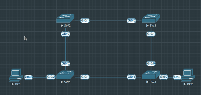
Regarding this topology, SW Gi0/1 (ive changed this iface cost to 50) is in ALT BLK state, and SW4 Gi0/1 is Desg FW

My Question is :

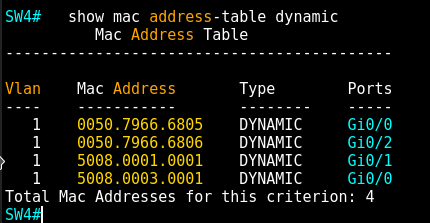
The screeshot above has the show mac address-table dynamic on SW4… Why this switch is receiving MAC ADD 5008.0001.0001 (SW1 BID) in port Gi0/1 that is FW but the other side SW1 Gi0/1 is ALT so, how could SW1 Gi0/1 forward this MAC ADD in this ALT state ? that’s because beside being in ALT state, BPDU are forwarded whatever the port state, therefore SW4 has the MAC ADD SW1 (BID) through this link ?

Hello Juan

One of two things may have happened here.

Remember that a MAC address entry exists in the MAC address table by default for 300 seconds or 5 minutes. If the topology was just initialized, it could be that before the STP topology stabilized and converged, some traffic did traverse the link from SW1 to SW4, and the MAC address table was populated. It could be that the entry simply hasn’t aged out and still appears in the table.

Assuming however that the topology has been stable for well over 5 minutes, then the above cannot be the case. As you suspected, BPDUs are indeed exchanged between SW1 and SW4 even though SW1’s Gi0/1 interface is in ALT BLK state. This exchange of BPDUs does indeed populate the MAC address table.

I hope this has been helpful!

Laz

1 Like

Hello,
I have a question please about TCN:
Switch is connected via 2 ports. One is root and one is backup. The root port goes down,
so it will get TCA via backup port to flush mac address table. But backup ports are receiving BPDUs right? So how can expire max age timer, when we are still getting the BPDUs. What exactly causes that the switch change his backup port to listening state again?
Thank you

Hello Eduard

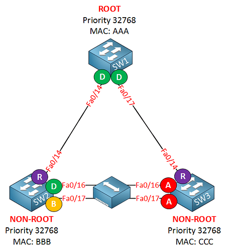
Do you really mean backup port? A backup port exists if you happen to have a hub between two switches like so:

The yellow port marked with a “B” is the backup port. More about the backup port can be found in the Rapid Spanning-Tree (RSTP) lesson.

I believe you meant “blocked port” correct? If so, then here is the answer to your question.

Actually no. If the root port goes down the local switch already knows that a topology change has occurred, since its own port has gone down. In this case, no MAC address flush is necessary. Remember TCNs are sent down the tree to switches that are unaware of any topology change. Indeed, the local switch itself will immediately reconverge its own ports so that the blocked port may become a designated port, or a root port (depending on what the rest of the topology looks like).

In other words if a topology change takes place that affects the local switch’s ports directly, then it knows a topology change has taken place. The TCN is only meaningful when a topology change takes place that is not on a directly connected interface.

It is the normal STP reconvergence process that causes the blocked port to revert to the listening and learning states again.

I hope this has been helpful!

Laz

1 Like

Hello Laz,
yes, sorry, I meant blocked port :slight_smile:
Thank you for explanation.

1 Like

I think im missing something :

At the beginning example on this lesson (R1 f0/16 shutdown towards the Root Bridge) it says R1 sends a TCN towards SW2 , until now for me is ok but why SW2 will reduce the aging time from 300 secs to 15 secs , i know the reason (to avoid traffic holes) but i mean this step isnt further ? The TCN has to reach the Root Bridge so the TCN from SW1 goes SW2 → SW4 and then to the Root Bridge. When it has reached the Root Bridge, the Root Bridge generates a Config BPDU with TC Flag set sending it downstream SW4 (it receives and reduce the aging from 300 to 15 secs), SW4 propagates to SW3 and do the same , and propagates it to SW1 and do the same .

But in this case the link between SW1 and SW3 (root bridge) goes down, so the root bridge also detects this TCN but it doesnt generate a TCN because is the root bridge, instead it generates the Config BPDU with the TC Flag set towards the only link remains up towards the SW2 , SW2 receives this BPDU and reduces its aging time from 300 to 15 secs , and propagates it towards SW3 (reduce aging to 300 to 15 secs) SW3 do the same towards SW1.

And now while writing the above another questions brings to my mind… if the above statement its right, what happens if this TCN toward the Root bridge cant be sent due all root bridge ports are down… new root election must be done ?

Hello Juan

In standard STP, the TCN originator sends a TCN upstream until it reaches the root. Once the root receives that TCN, it will begin sending configuration BPDUs out of all its ports. The TC flag is set on these BPDUs letting all switches in the topology know that a topology change has occurred. This is further described in the NetworkLessons note on the STP topology change process.

According to the official documentation, it is only when a switch receives the TC BPDU from the root that the aging timer for the MAC address table is reduced, and not when it receives a TCN from a downstream switch. The only exception is the switch on which the topology change was detected. In such a case, the age timer of the MAC address table on the originator of the TCN is immediately reduced.

So although SW1 sends a TCN and SW2 receives it, as shown in the debugs in the lesson, according to this, the age timer of the MAC address table of SW2 is likely not reduced. It is only when SW3 (the root) receives the TCN and sends out a TC BPDU that reaches SW2 that this will occur.

Note however, that the process from the point of view of SW3 is different. Normally, SW3 would try to send a TCN message out of its root port to reach the root bridge. Here, SW3 IS the root, so that isn’t really necessary. When this happens, because the root bridge itself detects the topology change, it will actually start sending out TC BPDUs on all its ports, thus it won’t actually wait for the TCN from SW1 to reach it.

If that is the case, that means that the topology is actually split into two sections that cannot communicate, or that have no link between them. If that happens then each section will indeed begin having an STP root election.

Please note that all of the above describe standard STP IEEE 802.1D. Remember, this version of STP is no longer used in production networks, however, its operation is good to know as a stepping stone to reach a good understanding of other types of STP.

I hope this has been helpful!

Laz

1 Like