Hoping you can help me with an example I came across but can’t get my head around. I’m using route maps (which I understand fine) but I have a question with the answer to this solution I hope you can share some information on.
Lets say we have the following Loopbacks:
Loopback-0 144.144.144.1 /29
Loopback-1 144.144.144.9 /29
Loopback-2 144.144.144.17 /29
Loopback-3 144.144.144.25 /30
Loopback-4 144.144.144.33 /28
Loopback-5 144.144.144.65 /27
And say we want to filter Loopback-0, Loopback-1, Loopback-2 using a standard ACL.
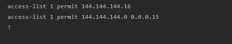
In the solution to this the ACL was configured like so:
The second entry I understand fine, 0.0.0.15 matches the block of 16, so 0-15.
But with regards to the first entry “144.144.144.16”, this is the network address. How does this work exactly?
When applying a standard access list, if you specify an address without any wildcard mask, then the assumed wildcard mask is 0.0.0.0. In other words, the first line of this access list is equivalent to:
access-list 1 permit host 144.144.144.16
Now if in your addressing scheme this is a network address, then it does seem kind of useless to apply such a statement in the access list since you will never have a source address equivalent to this. In my opinion, the first line should include a wildcard mask of 0.0.0.7 OR the .16 should simply become .17.
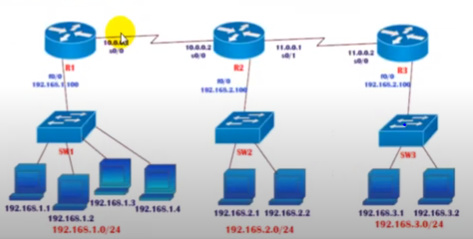
A) Deny the host 192.168.1.1 communicating with 192.168.2.0 (Host to Network ) Deny
B)Deny the host 192.168.1.2 communicating with 192.168.2.0 (Host to Network ) Deny
C) Deny the Network 192.168.3.0 communicating with 192.168.2.0 (Network to Network ) Deny
D) Permit all the remaining
Hope you understand what i want to acheive on above task ,Now i want to know , if we create standard ACL Separately on R1 & R3 Router like this ,
creating outbound ACL on R1 for given deny traffic
 R1 (config )#access list 16 deny host  192.168.1.1
                    #access list 16 deny host  192.168.1.2
R1 (config)#access list 16 permit any

Router R1 # Interface fa0/0
                   # ip access group 16 out
creating outbound ACL on R3 for given deny traffic
 R3 (config )#access list 17 deny host  192.168.3.0 0.0.0.255
R3 (config)#access list 17 permit any

Router R3 # Interface fa0/0
                   # ip access group 17 out
sir , please confirm can we acheive the task if we configure like this as above ,Means is they permit the traffic from Network 192.168.1.0 to 192.168.3.0 & vice versa because as i was creating acl on router 2 inbound they block the ip so i cannot considered it but if i apply on outbound interface of R2 they dont block ip 192.168.1.1 to ping 3.0 Network and vice versa , but in above configuration it restricted the ip to ping , why it so happen and help me to correct .
Basically i want to achieve above task by creating ACL Separately on R1 and R3 and as i know that in Standard ACL , Implematation is closed to destination and filter the source ip address .
Remember that access lists function on a per interface and per direction basis. This means that each interface can have one access list applied for the inbound direction, and one the outbound direction. Now each access list specifies whether the source or destination or both addresses are being matched.
For this particular example that you are stating, we see that the access list is:
applied to FE0/0 of R2
applied in an INBOUND direction
matches a source IP address within the range of 192.168.12.0/24
The parameters of the configuration are very specific, and refer only to this interface, on this router, in the specific direction, and with the specific match statements in the ACL.
Of course if you look at a communication from various points of view, these elements change, as you correctly stated above. But the parameters are clearly defined, and for these parameters, the directions of traffic flow are very specific.
Thanks for the answer but I am unable to understand it mean how do we know that ACL should be created to R 2 OUTbound interface for carry the specific traffic asked in task , Is dere any trick or idea behind that means we have Consider the lan connected to R2 as a destination and other lan respectively on R1 and R3 as a source , sir my concern s that why we cannot create ACL on R1 and R3 separately for specific and fullfing the task ,How do we know that in R2 and R3 if we create ACL they block the permit traffic .
How can we find it .Please share n more detail
Important Question
Hi Laz ,
As i go through with below post , I have one more doubt while create two acl list call on fa0/1 (outbound and inbound )
For example If i created access list deny 10.10.10.0 0.0.0.255 and apply inbound of interface ethernet 0/1
so the traffic that incoming the router through this interface and match with this statement would be drop. what about if the same traffic incoming the router through another port but it has to go out to destination through ethernet 0/1, so the router will forward or drop this traffic.
supposed i have a router with two interface fe0/0 and fe 0/1 with network 10.10.10.x & 10.10.20.x respectively
Now i am apply two acl list of deny the network that is
access list 1 deny 10.10.10.x 0.0.0.255
access list 2 deny 10.10.20.x 0.0.0.255
interface **fa0/1**
ip access group 1 out
ip access group 2 in
Noted
As earlier you said in your post that we can apply two acl list on same interface both inbound and outbound ,ya that fine we will create it .
Sir , what happened if you have traffic with a source IP address of 10.10.10.X & 10 .10.20 .x routed to in direction of fa0/1 and routed to out direction of fa 0/1 respectively .
How to implement and call in ACL ?
I need to implement this because same user asked question in above post but they have consider only one deny access list and want to restrict the traffic completely .
Hope you understand my concern .
Rgds
Shivam
The access lists you created are correct, however, the interfaces they are applied to will not give you the results you want. For example, access-list 16 will deny hosts 192.168.1.1 and 192.168.1.2 from reaching any other network, but you wanted to block them both from reaching 192.168.2.0/24 only. To fix this, this access list should be placed on R2, on the interface facing the 192.168.2.0/24 network, in an outbound direction. (The diagram is blurry, I think it say’s F0/0 but I’m not sure)
For access-list 17, you should not have the host keyword as this would not be accepted by the CLI. Also, this access list should also be applied on R2, on the interface facing the 192.168.2.0/24 network.
Because all access lists would be applied to the same interface and the same direction, they should be consolidated into a single access list with all three statements.
As i go through with below post , I have one more doubt while create two acl list call on fa0/1 (outbound and inbound )
For example If i created access list deny 10.10.10.0 0.0.0.255 and apply inbound of interface ethernet 0/1
so the traffic that incoming the router through this interface and match with this statement would be drop. what about if the same traffic incoming the router through another port but it has to go out to destination through ethernet 0/1, so the router will forward or drop this traffic.
supposed i have a router with two interface fe0/0 and fe 0/1 with network 10.10.10.x & 10.10.20.x respectively .
Now i am apply two acl list of deny the network that is
access list 1 deny 10.10.10.x 0.0.0.255
access list 2 deny 10.10.20.x 0.0.0.255
interface fa0/1
ip access group 1 out
ip access group 2 in
Noted
As earlier you said in your post that we can apply two acl list on same interface both inbound and outbound ,ya that fine we will create it .
Sir , what happened if you have traffic with a source IP address of 10.10.10.X & 10 .10.20 .x routed to in direction of fa0/1 and routed to out direction of fa 0/1 respectively .
How to implement and call in ACL ?
I need to implement this because same user asked question in above post but they have consider only one deny access list and want to restrict the traffic completely .
Hope you understand my concern .
Rgds
Shivam
Remember that you are using standard access lists which means that you can only specify the source address. You must apply the access list on R2 because you want to block traffic from the 192.168.1.1 host that is destined to the 192.168.2.0/24 subnet which hangs off of R2. If you were to apply it to R1, you would block all traffic sourced from this address. If you used extended access lists where you can specify both source and destination, then yes, you would apply it to R1.
If the traffic matches the access list in the direction of travel, then it will be dropped. Otherwise, it will not. You must look at each interface and each direction independently of any other interfaces. If it matches, it is dropped, if not it will go through.
For the access lists 1 and 2 you have created:
source address of 10.10.10.X outbound on Fa0/1 will not be dropped
source address of 10.10.10.X inbound on Fa0/1 will be dropped
source address of 10.10.20.X outbound on Fa0/1 will be dropped
source address of 10.10.20.X inbound on Fa0/1 will not be dropped
Simply look at the source address of the packet, look at the direction of travel, and look at the access list. Doing this will give you the result.
One important note: Your access lists 1 and 2 will actually drop all traffic unless you apply the permit ip any any statement at the end of each. Remember there is an implicit deny at the end of all ACLs.
I suggest you review all the lessons on ACLs again carefully and do some more experimentation using GNS3 or some other emulator. This is the best way to fully understand how they work, by experimenting with them.
i have a question of understanding. My first question is: can I create access lists on L2 switches in order to then create a rule that blocks internet access for a subnet or client, for example, or can access lists only be created on L3 or router? With QoS it means that the QoS marking should best be done on the edge part of the network, does this also apply to access lists or is there a “best practice” for this?
L2 switches do have the capability of creating and applying access lists that filter IP addresses. About a decade ago, I would have said that it depends on the IOS and the platform, but all Cisco L2 switches today support this. You can apply the ACL to the interface as you normally would, and it should function as expected.
The best practice for access lists depends on the type of access list you are using. Standard access lists, which filter traffic based on the source, should be placed as close as possible to the destination network/hosts where they are to be applied. This reduces needless processing of the ACL statements for all packets. Similarly, because extended access lists to filter traffic based at a location close to the source. This eliminates unnecessary bandwidth consumption of packets that would be dropped anyway. The earlier they are dropped, the less unnecessary bandwidth consumption takes place.
What is the reason standard access lists should be placed as close as possible to the destination? And why does it apply for standard access lists specifically, and not extended access lists?
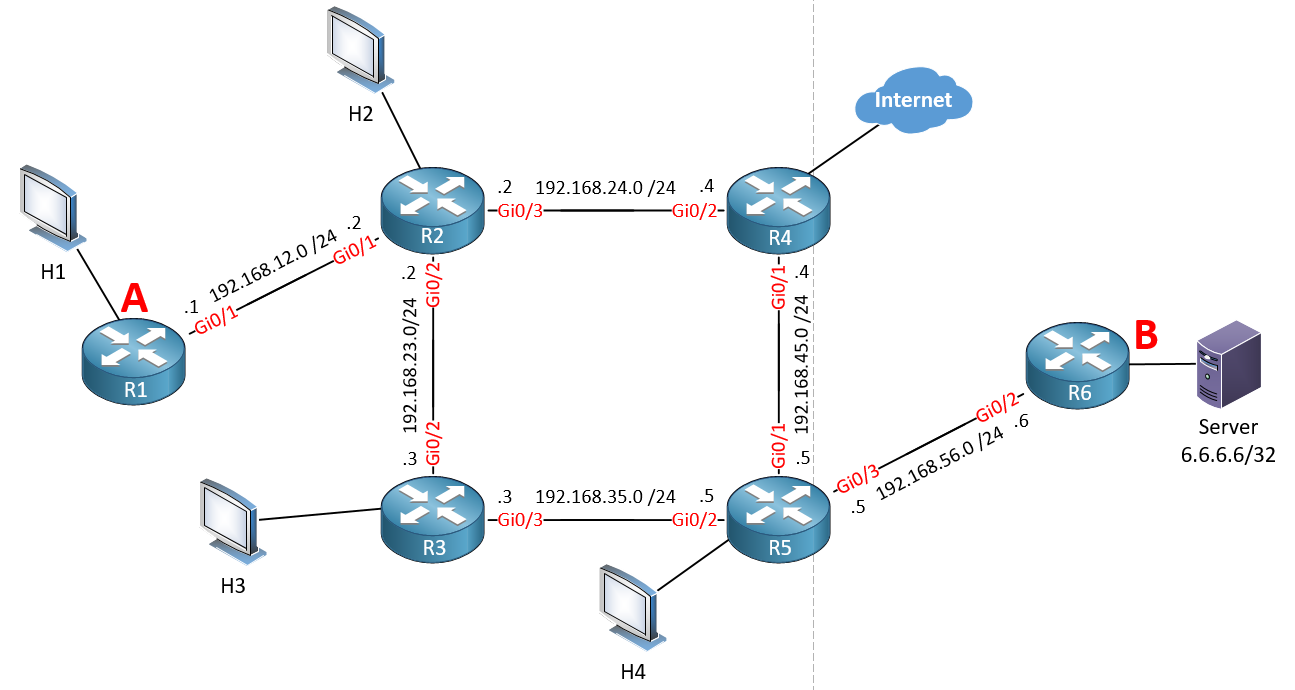
Now imagine that you want to block all Telnet traffic to the server with an IP address of 6.6.6.6 using a standard access list. The best practice says that you should apply it as close as possible to the destination because standard access lists examine only the destination IP. Looking at this topology, would it make sense to apply it at interface A on R1? You could, and thus any TFTP traffic from H1 going to the server will be blocked. However, there are a couple of problems with this:
All traffic that goes through interface A on R1 would be examined against the access list to see if it matches. This includes every single packet that H1 sends, even traffic destined for the Internet, and for other destinations on the network. This is unnecessary overhead that is being placed on the CPU of R1.
This access list will only examine traffic from H1. In order to check traffic from H2, H3 and H4, you have to apply the access-list again on R2, R3, and R5.
It would be more efficient to place the access list at interface B on R6. This way only a single access list needs to be applied and it will only examine and filter traffic that reaches the server, greatly increasing efficiency.
Now extended access lists examine both the source and the destination IP address. The logic is the same. If on the same topology you want to filter out all traffic that comes from H1, you don’t want to apply this to B because all traffic destined for the server will be filtered. But apply it at interface A closest to the source of the traffic. This way you also reduce the amount of unwanted traffic on your network. There is no need to have traffic from H1 traverse the whole network and reach the server only to be dropped. Better to drop the traffic before using network resources.
These three statements are completely different, so this is why only the first one is working as expected with your NAT configuration.
The first statement matches all addresses ranging from 192.168.12.0 to 192.168.12.255.
The second statement matches only the single IP address of 192.168.12.0. When you don’t specify a wildcard mask, the command assumes a wildcard mask of 0.0.0.0. So, the following three commands are identical, since all three match and permit the single address of 192.168.12.0:
Now the third statement is interesting. Remember that a wildcard mask indicates that wherever there is a “0” the bits of the address must remain the same. Wherever there is a “1” we can have anything. (This is the opposite of a subnet mask). With a wildcard mask of 255.255.255.0, where the last octet is all zeros in binary, this means that the last octet must remain the same and the first three octets can be anything.
Taking a look at 192.168.12.0, this means that the access list will match and permit any IPv4 address that has the last octet of zero. So it will match the following IPv4 addresses:
In other words, every combination of IPv4 address where the last octet is zero. This is not matching at all what you want for your NAT, so this is why it is not working. Take a look at this NetworkLessons note on ACL wildcard masks for more information.
I understand that you are essentially asking “How does a router determine the source address when we ping from that router without specifying a source?”
The router will always use the IP address of the exit interface as the source IP address of the ping. The exit interface is determined based on the routing table. Take a look at this NetworkLessons note on ping troubleshooting concepts for more details.
Even though this post is six years old, thanks to @NetworkGuy for noticing it is unanswered.
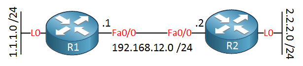
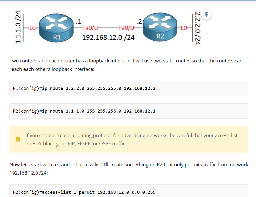
This command is telling R1 that in order to reach the 2.2.2.0/24 network, the next hop it must use is the 192.168.12.2 address, which is the IP address of Fa0/0 of R2. So if R1 receives an IP packet with a destination address within the 2.2.2.0/24 network, it will forward it to 192.168.12.2, which is R2 which is correct.
Similarly, the static route applied to R2 is correct:
This is because it instructs R2 to send any packets destined for the 1.1.1.0/24 network to 192.168.12.1 which is R1 which is correct. Does that make sense?
Can you advised why we can not permit traffic from network 192.168.12.0/24 on outbound interface of Router 2 , if traffic is flow from R1 to R2 , I m confused how to elect inbound and outbound interface while creating ACL , can you help me please with some example and scenerio ??
Can you help me to understand the question asked by hroger very diffuct to undertsand seems some confusion in looback why acl not applied on loop back interface ?