Troubleshooting AD Redistribution

Hi Rene and staff,

i want to add another comment for the final solution. Perhaps it could help someone
"
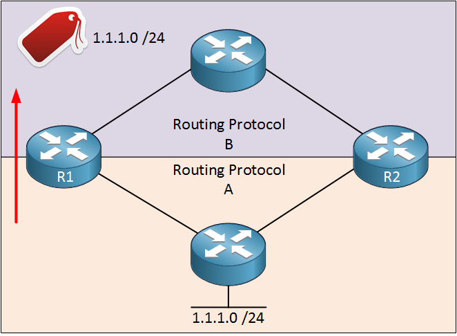
R4 will use the EIGRP external entry (AD 170) for 1.1.1.0 /24. R2 and R3 both redistribute 1.1.1.0 /24 into EIGRP, the route that R4 installs depends on the seed metric
"
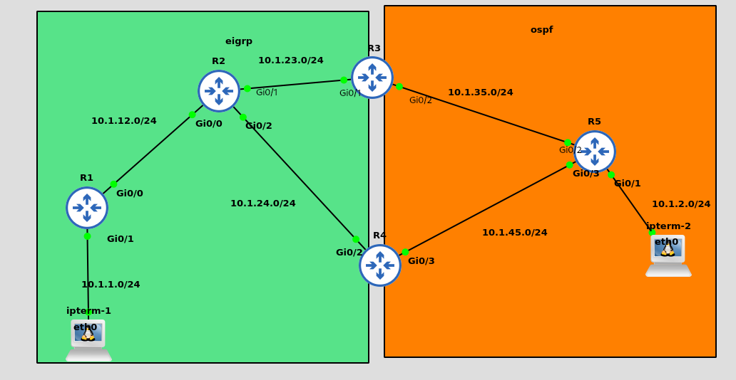
In the lesson R2 redistribute RIP into EIGRP with BW=1000
And R3 redistribute OSPF into EIGRP with BW=1500
So in my opinion R4 will install the route via R3
I don’t know why so low values are used in the lesson with FastEthernet (?)

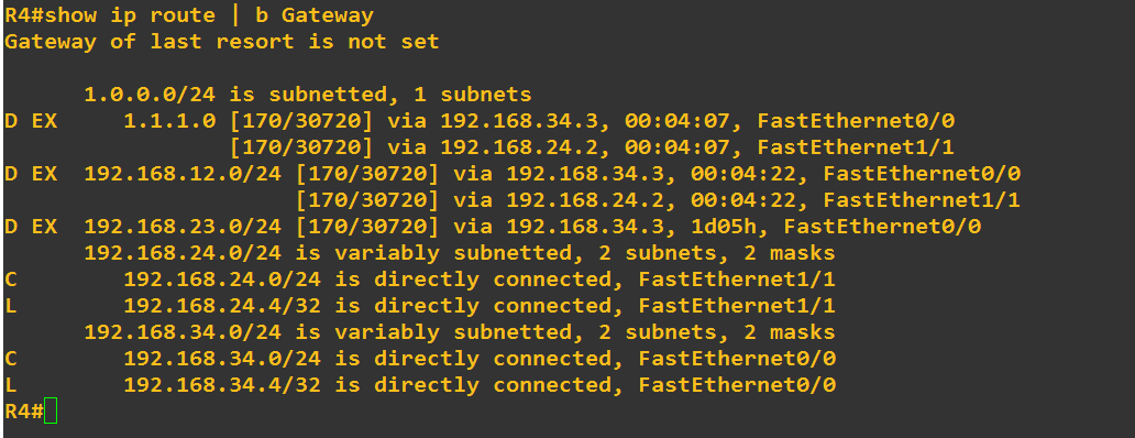
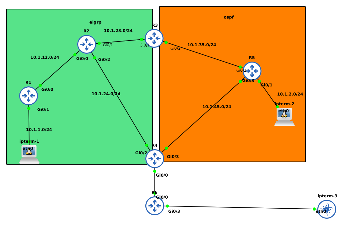
But in my GNS3 lab, i set R2 and R3 both to redistribute 1.1.1.0/24 into EIGRP with the same composite metrics (BW= 100 000, DL, etc…) So, with this topology and the same redistribution composite metrics and the same K-values, from the perspective of R4 there are two paths with the same metric, and EIGRP could load balance between these paths. Let’s find the R4’s RIB from my lab (in my lab the name of interfaces are not the same)
Image13

Regards

2 Likes

Hello Dominique

Even if the route on R4 is installed and removed so quickly that you can’t see it with a show ip route command, if you issue the ip route profile command, as shown in the lesson, it will show you how many times the route was installed and removed. Do you see these counters going up as they should in your topology?

If so, then the only thing I can say is that it is just by chance, or for some reason, the route remains in the routing table for such a small amount of time, compared to R2. Remember that the route flapping in R2 is occurring between routes that are learned between RIP and OSPF, where on R4, the route flapping is occurring with EIGRP only. The variation in timers that are used by the particular protocols plays a role in how quickly a routing protocol converges. It can be said that EIGRP converges very quickly, and for this reason, you cannot “catch” the route in the table.

I hope this has been helpful!

Laz

Hello Dominique

Yes you are correct.

Split horizon says, as you very well know, that you cannot learn about a route from the same interface that you advertised it out of. Because we have a loop here, R2, R3, R4, each router will always learn about 1.1.1.0/24 from an interface from which it did not learn about it. It learns about it from one interface, and informs the next router from another interface. This happens on R2, R3, R4, and then again on R2, from an interface other than the one it was sent out of. Regardless of which routing protocol is being used, the fact that we have a physical loop with redistribution can allow a route to cause such a routing malfunction and split horizon is helpless to rectify it.

I hope this has been helpful!

Laz

Hello Rene/Laz,

I configured the same AD redistribution topology on GNS3 and resolved the issue using the first method i . e by applying a lower AD for the RIP route from R1 for 1.1.1.0/24 and I am seeing results in the routing table that R2 is learning 1.1.1.0/24 from R1 with the AD 100. All good there however I am not able to ping 1.1.1.0/24 from R3 and R4 even though these routers have route to 1.1.1.0/24 in their routing table. Also I redistributed connected network under RIP on R2 but 192.168.23.0/24 is still unreachable from R1. All configs were done exactly per the lesson. Can you please help clarifying this issue?

R3#ping 1.1.1.1
Type escape sequence to abort.
Sending 5, 100-byte ICMP Echos to 1.1.1.1, timeout is 2 seconds:
.....
**Success rate is 0 percent (0/5)**

R3#sh ip route | begin Gateway
Gateway of last resort is not set

      1.0.0.0/24 is subnetted, 1 subnets
**D EX     1.1.1.0 [170/2636800] via 192.168.34.4, 00:08:08, Ethernet0/1**

R4#ping 1.1.1.1
Type escape sequence to abort.
Sending 5, 100-byte ICMP Echos to 1.1.1.1, timeout is 2 seconds:
.....
**Success rate is 0 percent (0/5)**

R4#sh ip route | begin Gateway
Gateway of last resort is not set

      1.0.0.0/24 is subnetted, 1 subnets
**D EX     1.1.1.0 [170/2611200] via 192.168.24.2, 00:09:48, Ethernet0/1**

R1#ping 192.168.23.2
Type escape sequence to abort.
Sending 5, 100-byte ICMP Echos to 192.168.23.2, timeout is 2 seconds:
.....
**Success rate is 0 percent (0/5)**

R1#ping 192.168.23.3
Type escape sequence to abort.
Sending 5, 100-byte ICMP Echos to 192.168.23.3, timeout is 2 seconds:
.....
**Success rate is 0 percent (0/5)**

I found the issue and fixed. It was a silly mistake I made on R2. I missed “version 2” command on R2 and R1 was configured with version 2. Now I have full connectivity after I configured version 2 command on R2. Thank you anyway!

R3#ping 1.1.1.1
Type escape sequence to abort.
Sending 5, 100-byte ICMP Echos to 1.1.1.1, timeout is 2 seconds:
!!!!!
Success rate is 100 percent (5/5), round-trip min/avg/max = 1/1/2 ms

R4#ping 1.1.1.1
Type escape sequence to abort.
Sending 5, 100-byte ICMP Echos to 1.1.1.1, timeout is 2 seconds:
!!!!!
Success rate is 100 percent (5/5), round-trip min/avg/max = 1/1/1 ms

R1#sh ip route | begin Gateway
Gateway of last resort is not set

      1.0.0.0/8 is variably subnetted, 2 subnets, 2 masks
C        1.1.1.0/24 is directly connected, Loopback0
L        1.1.1.1/32 is directly connected, Loopback0
      192.168.12.0/24 is variably subnetted, 2 subnets, 2 masks
C        192.168.12.0/24 is directly connected, Ethernet0/0
L        192.168.12.1/32 is directly connected, Ethernet0/0
R     192.168.23.0/24 [120/1] via 192.168.12.2, 00:00:03, Ethernet0/0
R     192.168.24.0/24 [120/1] via 192.168.12.2, 00:00:03, Ethernet0/0
R     192.168.34.0/24 [120/1] via 192.168.12.2, 00:00:03, Ethernet0/0

Hello Philip

Thanks for sharing your solution with us, it’s always helpful to see your solutions to the problems that you face. If you have any other issues, you know where to find us!

Laz

I am wrong or we can fix this issue with tag the redistribution?

Hello Angelo

Yes, you could use route tagging to resolve this issue. You could tag the route when it is being redistributed from RIP to EIGRP on R2, so that when this is re-redistributed from R3 to R2 via OSPF, it is simply not accepted.

Although this solution would be fine for this topology, making changes to the AD would be more appropriate than using tagged routes. This is because in the event that a specific route does indeed fail, you would want the alternate route to be installed in the routing table. When using route tagging, the alternate route would not be installed, however by adjusting the ADs, that alternate route would be installed, making this solution a more robust and preferable one.

I hope this has been helpful!

Laz

Awesome Lesson!!
Question, is there a solution using Tagging/filtering instead of modifying the AD?
I came accross this question on the CCNP exam and the only options for solution was using filtering, thanks in advance.

Hello Patrick

Yes, you can use filtering to solve this problem. Simply filter out the 1.1.1.0/24 route learned by R2 via OSPF using an incoming route map on the Fa0/0 interface of R2. That way, R2 will never learn about 1.1.1.0/24 from R3, and it will only learn it directly from R1, thus no flapping routes.

Route tagging will not work because a tag will only exist within the routing domain of a particular routing protocol. Once a route is redistributed into another routing domain, that tag information is no longer there. Tags are useful for preventing a route from being readvertised back into the routing domain from which it was originally learned. More about route tagging can be found here:

I hope this has been helpful!

Laz

Hello Rene,
Thank you for this lesson.

I have a question about this output show ip route profile I understood your explanation about Change/Interval the first column will represent changes and the rest will be the intervals. However it will make more sense if the first column is the intervals and the rest the changes
for example from your first out put from router 2 we can say that in two intervals of 5 seconds we have changed the FW-Path 174 times.
Can you please confirm ?

Hello Divier

It is true that the output is a little bits strange, but let me try to clarify.

The Change/interval column is known as a frequency bucket. Each bucket for each category of changes to the routing table is incremented every time a particular event occurs X number of times within a sampling interval. For example,

  • every time a Fwd-path change takes place once within a sampling interval, the value in the Fwd-path change column that corresponds to Change/interval 1 will be incremented.
  • every time a Fwd-path change takes place twice within a sampling interval, the value in the Fwd-path change column that corresponds to Change/interval 2 will be incremented.
  • every time a Fwd-path change takes place three times within a sampling interval, the value in the Fwd-path change column that corresponds to Change/interval 3 will be incremented.

and so on.

The Change/interval bucket 0 is a special case, where it indicates the number of sampling intervals in which there were no changes for that particular change type.

Let’s take a look once again is the output from the lesson:

R2#show ip route profile
IP routing table change statistics:
Frequency of changes in a 5 second sampling interval
-------------------------------------------------------------
Change/   Fwd-path  Prefix   Nexthop  Pathcount  Prefix
interval  change    add      change   change     refresh
-------------------------------------------------------------
0         975       983      1165     983        1165
1         16        182      0        182        0
2         174       0        0        0          0
3         0         0        0        0          0
4         0         0        0        0          0
5         0         0        0        0          0

The value of 174 in row 2 indicates that a Fwd-path change occurred twice within the sampling interval 174 times.

Similarly, a Prefix add occurred once within the sampling interval 182 times.

Also, there were 1165 sampling intervals that elapsed with no next-hop changes.

In this output, the Change/Interval is sequential, but it is not necessarily so. Take a look at this Cisco command reference which shows additional detail in how the output appears and is interpreted.

https://www.cisco.com/c/en/us/td/docs/ios/iproute_pi/command/reference/iri_book/iri_pi2.html#wp1042290

I hope this has been helpful!

Laz

Hi

I’ve built a GNS3 lab to reproduce a routing loop intentionally between EIGRP and OSPF .

The topology is like this one

I’ve modified internal and external ADs:

  • OSPF : distance 80
  • EIGRP: distance eigrp 190 190

After the mutual redistribution, one of these routers (R1 or R2) install the suboptimal route, but the other one still maintain the eigrp route.

Even if I clear the eigrp adjacency the network still prevent loops.

Why my network is still alive ? :sweat_smile:

Hello Giovanni

Take a look at this NetworkLessons note on redistribution and the routing table for an explanation of what is happening.

This does not mean that such a topology is safe from routing loops. The “other router” that is maintaining the EIGRP route may be OK, but if you have additional routers in that routing domain, those routers will install the suboptimal route as well.

I hope this has been helpful!

Laz

Hi Lazaros,

This is my actual GNS3 lab

I’ve tried to add other routes (11.11.11.11 on R1 and 55.55.55.55 on R5), but R2 always know that he have to send traffic to R3, that is the router that maintains EIGRP routes.

R2#show ip route
....
      11.0.0.0/32 is subnetted, 1 subnets
D        11.11.11.11 [90/130816] via 10.1.12.1, 00:32:03, GigabitEthernet0/0
      55.0.0.0/32 is subnetted, 1 subnets
D EX     55.55.55.55 [170/3072] via 10.1.23.3, 00:30:56, GigabitEthernet0/1

R2#show ip eigrp topology all-links 
...
P 11.11.11.11/32, 1 successors, FD is 130816, serno 171
        via 10.1.12.1 (130816/128256), GigabitEthernet0/0
        via 10.1.24.4 (2560000512/2560000256), GigabitEthernet0/2
P 55.55.55.55/32, 1 successors, FD is 3072, serno 177
        via 10.1.23.3 (3072/1536), GigabitEthernet0/1
        via 10.1.24.4 (2560000512/2560000256), GigabitEthernet0/2

R5#show ip cef 11.11.11.11
11.11.11.11/32
  nexthop 10.1.35.3 GigabitEthernet0/2

These are the routing tables of the redistributing routes.

R3#
      11.0.0.0/32 is subnetted, 1 subnets
D        11.11.11.11 [190/131072] via 10.1.23.2, 00:26:21, GigabitEthernet0/1
      55.0.0.0/32 is subnetted, 1 subnets
O        55.55.55.55 [80/2] via 10.1.35.5, 00:25:09, GigabitEthernet0/2

R4#
      11.0.0.0/32 is subnetted, 1 subnets
O E1     11.11.11.11 [80/3] via 10.1.45.5, 00:28:39, GigabitEthernet0/3
      55.0.0.0/32 is subnetted, 1 subnets
O        55.55.55.55 [80/2] via 10.1.45.5, 00:27:32, GigabitEthernet0/3

As you can see, R4 install a sub-optimal routing to 11.11.11.11 and everything works because R2 know that have to send traffic to R1 and not pay attention to the route redistribuited by R4.

Why this is happening? I didn’t catch that.

Thanks.

Hello Giovanni

This is expected behavior. Remember that R3 is doing the redistribution and not R4. The router that does the redistribution does not have its routing table affected by any of the redistribution parameters, including AD. This is why you see R3 with the correct routing to each of the 11.11.11.11 and 55.55.55.55 destinations.

R4 on the other hand prefers to send packets destined to 11.11.11.11 to R5 simply because the AD of the OSPF-learned networks is set to 80, which is less than the default of 90 for EIGRP-learned routes. It has learned about 11.11.11.11 from R2, but with an AD of 90.

Now why does R2 prefer to send traffic to R3 rather than R4? Because R4 is not advertising a route to 11.11.11.11 within the EIGRP realm, for two reasons:

  • R4 is not performing redistribution so the 11.11.11.11 route learned from OSPF is not being re-redistributed into EIGRP
  • Also R4 has learned about 11.11.11.11 via EIGRP (from R2) but due to the split-horizon rule, it won’t re-advertise it back to R2.

Now you mention that everything works, and that may be true for communication to and from the 55.55.55.55 and 11.11.11.11 networks, however, the fact that R4 sends 11.11.11.11 to R5 as a next-hop is not good. What if you have a network that’s hanging off of R4? It will try to reach 11.11.11.11 via R5, something that is not desirable.

So the topology may work, but it still has problems that must be resolved.

I hope this has been helpful!

Laz

Hi Laz,
My goal in this lab is to generate a routing loop between ospf and eigrp.
I disabled split horizon on all links in the eigrp topology, and also redistribution is performed by R3 and R4.

R3#show running-config | section router
router eigrp 1
 network 3.3.3.3 0.0.0.0
 network 10.1.23.0 0.0.0.255
 redistribute ospf 1 metric 2000000 1 255 1 1500
 distance eigrp 190 190
router ospf 1
 redistribute eigrp 1 metric 1 metric-type 1 subnets
 network 10.1.35.0 0.0.0.255 area 0
 distance 80
R3#

R4#show running-config | section router
router eigrp 1
 network 10.1.24.0 0.0.0.255
 redistribute ospf 1 metric 1 1 255 1 1500
 distance eigrp 190 190
router ospf 1
 redistribute eigrp 1 metric 1 metric-type 1 subnets
 network 4.4.4.4 0.0.0.0 area 0
 network 10.1.45.0 0.0.0.255 area 0
 distance 80
R4#

How does R2 set this matric for ospf networks to R4?

P 55.55.55.55/32, 1 successors, FD is 3072, serno 177
        via 10.1.23.3 (3072/1536), GigabitEthernet0/1
        via 10.1.24.4 (2560000512/2560000256), GigabitEthernet0/2

Sorry but I dont understand. :innocent:

Thanks

Finally I got it :upside_down_face:

R1#traceroute 192.168.1.100
Type escape sequence to abort.
Tracing the route to 192.168.1.100
VRF info: (vrf in name/id, vrf out name/id)
  1 10.1.12.2 8 msec 10 msec 11 msec
  2 10.1.23.3 11 msec 14 msec 9 msec
  3 10.1.35.5 9 msec 16 msec 10 msec
  4 10.1.45.4 15 msec 12 msec 13 msec
  5 10.1.24.2 15 msec 23 msec 10 msec
  6 10.1.23.3 11 msec 16 msec 13 msec
  7 10.1.35.5 15 msec 16 msec 18 msec
  8 10.1.45.4 21 msec 18 msec 27 msec
  9 10.1.24.2 21 msec 21 msec 9 msec
 10 10.1.23.3 21 msec 24 msec 20 msec
 11 10.1.35.5 17 msec 18 msec 25 msec
 12 10.1.45.4 31 msec 31 msec 19 msec
 13 10.1.24.2 25 msec 38 msec 23 msec
 14 10.1.23.3 22 msec 22 msec 37 msec
 15 10.1.35.5 41 msec 33 msec 45 msec
 16 10.1.45.4 47 msec 32 msec 44 msec
 17 10.1.24.2 52 msec 42 msec 41 msec
 18 10.1.23.3 51 msec 31 msec 32 msec
 19 10.1.35.5 41 msec 54 msec 50 msec
 20 10.1.45.4 52 msec 46 msec 53 msec
 21 10.1.24.2 55 msec 54 msec 50 msec
 22 10.1.23.3 52 msec 47 msec 52 msec
 23 10.1.35.5 53 msec 53 msec 57 msec
 24 10.1.45.4 81 msec 51 msec 55 msec
 25 10.1.24.2 48 msec 58 msec 62 msec
 26 10.1.23.3 47 msec 60 msec 67 msec
 27 10.1.35.5 76 msec 67 msec 80 msec
 28 10.1.45.4 59 msec 64 msec 82 msec
 29 10.1.24.2 90 msec 62 msec 71 msec
 30 10.1.23.3 68 msec 63 msec 67 msec
R1#

To generate a loop was needed another redistribution to the mix, so I configured and redistributed a static route to 192.168.0.0/24.

This is my new topology.

Hello Giovanni

The metrics you see in the output of the show ip eigrp topology command are a result of the redistribution values you configured using the redistribute ospf 1 metric 1 1 255 1 1500 command. Specifically, if you plug in the values you used into the EIGRP formula, you will see that you get the result you show in your output.

The redistribution command you used is the following:

redistribute ospf 1 metric 1 1 255 1 1500

where

  • bandwidth = 1 Kbps
  • delay = 1
  • load = 1
  • reliability = 255

If you plug those into the EIGRP formula, you get 2560000025.6 rounded up to 2560000026.

Now the value shown in the EIGRP topology table for FD and reported distance includes an additional cost between R4 and R2, so it is slightly higher than this calculated value.

Similarly, if you plug in the values you used in your redistribute ospf 1 metric 2000000 1 255 1 1500 command on R3, you will get the resulting metric you see in your topology table.

For more information on how EIGRP generates metrics, take a look at this lesson:

I hope this has been helpful!

Laz

1 Like