Hi Lazaros,
Thanks for explaining. My doubt got cleared.
Regards,
kishor
Hi Lazaros,
Thanks for explaining. My doubt got cleared.
Regards,
kishor
Hello Kishor.
Glad I could be of help!
Laz
Hi Rene,
As you told frame will be tagged on the trunk port.
If we have source and destination on same switch within same vlan, then there will be no tagging right ?
I read some where that access port will tag the frame with vlan id,trunk port will only carry all vlans traffic pls clarify
Hello Rohitenu.
To answer your first question, yes. If you have a souce device and a destination device on the same switch and on the same VLAN, then the frames will NEVER be tagged.
An access port will NOT tag frames. A trunk port WILL tag frames. It must tag them because that is the method by which a trunk discerns between frames on different VLANs.
I hope this has been helpful.
Laz
19 posts were merged into an existing topic: 802.1Q Encapsulation Explained
Hi Laz,
Very good to read your explanation.
Just one question …If there are 2 or more vlans(eg. vlan 10 and vlan20) for which a trunk exists between 2 switches (SW1 and SW2), does using intervlan routing means that “interface vlan 10” and “interface vlan 20” to be configured in both the switches or any one of the switch ? Or can it also be that “interface vlan 10” is configured in SW1 and “interface vlan 20” is configured in SW2 ?
Thanks & Regards,
Abc
Hello Abey
It all depends on your network topology. If you have two layer three switches connected via a trunk with allowed VLANs 10 and 20, then you must choose which switch will do the routing between the VLANs. The switch that will perform the routing will have to have the Switched Virtual Interfaces (SVIs) on them. (SVIs are the VLAN interfaces configured using the “interface vlan X” command). THey should be configured with IP addresses and those addresses should be used by the devices on each VLAN as the default gateway.
There is no need to create SVIs for both VLANs on both switches. Actually, this may cause some problems in routing. If you create one SVI in one switch and one on the other, then intervlan routing will not take place.
The most common configuration is choosing one switch to do all the routing and creating all the SVIs on that switch.
I hope this has been helpful!
Laz
Hi Laz,
Thank you very much for your reply. It really helped.
Regards,
Abc
Hello Laz,
I have couple of questions regarding trunking. Let’s say I have three switches connected one after another as below:
ACCESS PORT(VLAN 10)======SWITCH_1------(TRUNK PORT)-----SWITCH_2------(TRUNK PORT)----SWITCH_3=====ACCESS PORT(VLAN 10)
S1 is sending a frame to S3 in Vlan 10.
So, when SWITCH_1 is receiving traffic on the access port, before it sends the frame to SWITCH_2, it will tag the frame with VLAN 10 . Switch_2 will receive the frame and forward it to Switch_3 through the trunk port. My question is,
Is Switch_2 going to remove the Vlan 10 tag when it receives the frame on the trunk port connected to Switch_1?
Is Switch_2 going to tag the same frame with Vlan 10 once again before it sends out to Switch_3?
Second Question:
In case of router on a stick, Does a router tag a frame with the Vlan ID before it sends out to the connected switch through the trunk link? If the router does not tag the frame, the switch will not know what Vlan the frame belongs to.
router on a stick
access port(Vlan 10)=====SWITCH_1---------(TRUNK PORT)---------(ROUTER_1)-------------(ROUTER_2)
G0/0.10
INBOUND TRAFFIC <<<===============================================R_2 IS SENDING TOWARDS A HOST CONNECTED TO SWITCH_1 IN VLAN 10.
Hello Laz,
One more question. Does a switch tag broadcast frames before it sends frames out to another switch through a trunk port in the same VLAN?
Hello AZM
The quick answer to your first question is yes and yes.
When a tagged frame enters a trunk port, the tag is always removed. Using your example of a tagged frame with VLAN 10, the switch checks to see a couple of things:
(Keep in mind that in both of the above cases, whether a frame actually exits from one of these ports also depends on the mac-address table. If you need clarification on this, you can check out Rene’s lesson on how a switch learns MAC addresses.)
Concerning your second question:
The answer is yes. When you configure subinterfaces on the router itself, you are also enabling dot1q encapsulation, which essentially allows the router to perform VLAN tagging on the specific subinterface. You also specify the VLAN associated with the subinterface so that the appropriate VLAN can be tagged.
I hope this has been helpful!
Laz
Hello again AZM
The answer is yes. Let’s say there is a broadcast that comes into a switch on VLAN 10. This broadcast will have its tag removed, and the switch will search for:
I hope this has been helpful!
Laz
Thank you so much Laz for the great explanation.
Azm
Hello Laz,
The order of operations between mac-address table lookup and routing lookup in a layer 3 switch while routing between SVIs is little bit confusing and I have a few questions to clarify myself.
Let’s say we have a topology like below:
Host A (Vlan 10)-----------------SWITCH_1----(trunk)-------SWITCH_2----------HostB (Vlan20)
Here both switches have vlan 10 and vlan 20 configured.
Thank you so much in advance.
Azm
When Switch 1 will receive a packet from Host A destined to Host B, what would Switch 1 do first? Would it look at the mac address table first or it will look at the routing table since it has the routing capability? Please explain.
Thank you so much in advance.
Azm
Hello Azm
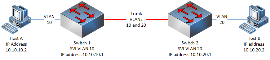
Here is the topology that you described.
Except for the labeling in the diagram, the network has the following elements:
Keep in mind that the order of operations of MAC address-table lookup and routing is based on the order in which encapsulation and de-encapsulation take place.
Let’s go through it step by step. If Host A sends a packet to 10.10.20.2, it will
The hosts will not be able to talk to each other.
Routing in its simplest form is just the process by which a layer 3 device chooses the egress port through which to send a packet based on its destination address. This means that in order for routing to take place, there must be at least two layer 3 ports (virtual or not) on a device - one to be the incoming port and one to be the outgoing port.
The above topology has both layer 3 switches with only one layer 3 port each - the SVI port. So all packets that arrive at the SVI port to be routed will be dropped. The best and most straightforward way to allow the above topology to work is to choose one of the two switches to perform inter-VLAN routing, and configure both SVI ports (VLAN 10 and 20) on that switch providing for both an ingress port and egress port. Just make sure that the default gateways are configured correctly on the hosts as well.
I hope this has been helpful!
Laz
Hello Laz,
As usual, spectacular.
When Host A will communicate with host B or vice versa, what would be the order of operations between mac-address table lookup and arp lookup while both Vlan 10 and Vlan 20 SVIs are configured on the same switch (either Switch_1 or Switch_2)?
Thank you so much.
Azm
Hello Azm.
The order of operations will always be in the same order as the de-encapsulation that occurs when the switch receives the frame. Let’s go through the process assuming that the SVIs for VLAN 10 and VLAN 20 are both configured on Switch 1.
Host A sends a packet to Host B
I believe that this step by step description will give you a better idea of the order of operations that occur when routing (layer 3 de-encapsulation) and when switching (layer 2 de-encapsulation).
I hope this has been helpful!
Laz
Hello Laz,
Thanks a lot once again. Your write up has been pretty useful. One quick question. Let’s say IP ROUTING is enabled on Switch B and it also has a few SVIs configured for other VLANs that are connected to Switch B, but Switch B does not have any SVIs configured for VLAN 10 and VLAN 20 both. In this case, What will happen when Switch B will receive a packet from Switch A destined to host B? Will Switch B look at the routing table first and drop the packet since it will not have any routing entry or it will look at the mac- address table first, find the entry for a particular switch port and send the frame out of that port accordingly? What will happen to the return traffic that is coming from Host B destined to Host A? Will Switch B not look at the routing table to look for a routing entry for 10.10.10.2 first when Switch B receives a packet from Host B destined to Host A and drop the packet since it will not have any routing entry for it or Switch B will look at the mac-address table and forward the frame accordingly? My problem is when it comes to solid layer 3 or layer 2 devices, I am fine with them, but when it comes to layer 3 devices, I get confused.
Thanks a lot Laz for your time once again.
Azm
Hello again AZM
I’m always glad I could be of help! ![]()
If Switch B were configured as you describe above, the functionality would be EXACTLY the same as described in my previous post. This is because when the frame leaves the VLAN 20 SVI interface on Switch 1, its destination address (10.10.20.2) is in the SAME subnet as the VLAN 20 SVI interface (10.10.20.1). This means that it is on the last hop of the trip and no additional routing is necessary. So when this frame exits the trunk port of Switch 1, it will have in its header the destination MAC address of Host B. When the frame reaches the trunk port of Switch 2, only a MAC address table lookup will take place within the switch which will direct the frame out of the port where Host B is connected.
On the return trip, when Host B sends a packet to 10.10.10.2, it will see that it is not in the same subnet as its own, so it will send the packet to the default gateway configured in its network settings, which is the VLAN 20 SVI port on Switch 1 (10.10.20.1). When it encapsulates the packet in a frame it will place the MAC address of this SVI port as the destination MAC address. The frame will go to the VLAN 20 SVI port on Switch 1, become de-encapsulated and will go through the routing table much like it did in the initial trip from Host A to B.
I believe the following principles will help you out in understanding where layer 2 and layer 3 addressing functionalities take place:
When a packet is sent from one host to the other, the destination IP address remains the same for the whole trip. The destination MAC address however changes for each hop.
When one host sends a packet to another, each hop requires the use of the next hop router’s MAC address as the destination address. That means that for all hops except for the last one, routing will take place. Thus de-encapsulation will take place to layer 3, routing tables will be looked up and packets will be routed. On the LAST hop, the destination MAC address is always the MAC address of the host. In that case, there will be no routing, no layer 3 de-encapsulation. De-encapsulation will occur on the destination host itself all the way up to the application layer.
I hope this has been helpful!
Laz