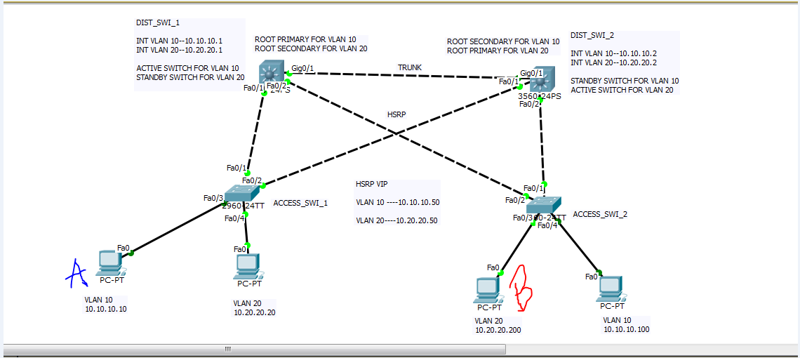
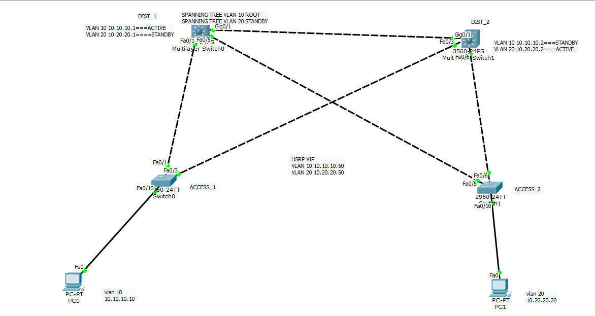
In this topology, I have HSRP configured between DIST_1 and DIST_2 switches. DIST_1 is the active switch for vlan 10 and DIST_2 is the active switch for vlan 20. That means, DIST_1 switch will act as the default gateway for vlan 10 and DIST_2 switch will act as the default gateway for vlan 20. All the IP address information is mentioned in the topology including spanning tree. I also have two access layer switches and they both are solid layer 2 switches.
Vlan 10 : 10.10.10.0/24
Vlan 20: 10.20.20.0/24
Question:
Let’s say PC A (10.10.10.10 / VLAN 10) is trying to communicate with PC B (10.20.20.200 / VLAN 20). So PC A will send the packet to its active default gateway located in DIST_A. Now DIST_A will look at its routing table and find the route for 10.20.20.0/24. Even though DIST_A has the route for destination(PC B), the active default gateway for vlan 20 is in DIST_B switch. What would DIST_A switch do next to forward the packet to the destination PC B? How would the traffic flow between PC A and PC B? Please describe it.
The process will be much the same, however, in this case, Host A will have a default gateway of 10.10.10.50 and Host B will have a default gateway of 10.20.20.50. Each of these IP addresses correspond to the MAC address of the currently active router. So it is this MAC address that will be placed in the destination MAC address field. Let’s look at it step by step.
Host A prepares a packet with destination IP address 10.20.20.200. It is on a different subnet, so when encapsulating, the destination MAC will be that of the default gateway (10.10.10.50). Using ARP, this MAC is learned and placed in the packet. This is the MAC that corresponds to the active router for VLAN 10, which is DIST_1
The destination IP address of 10.20.20.200 will be used to look in the routing table of DIST_1 and see where this should be routed. The routing table shows that this should egress from the VLAN 20 SVI port on DIST_1 which has an IP address of 10.20.20.1. Note this is NOT the virtual HSRP interface, but the SVI interface on the switch.
Encapsulation occurs, destination MAC address of Host B is inserted in the field and the MAC address table lookup takes place. Based on STP, whichever path is not blocked will be taken.
The frame reaches ACCESS_SW2 and using another MAC address lookup it knows to send the packet from the port connected to Host B
The return trip works much the same way, but the DIST_1 and DIST2 switches are reversed. I’ll go through it quickly
Host B sends a packet with destination IP address 10.10.10.10. MAC of default gateway (10.20.20.50) is destination MAC. This is the MAC that corresponds to the active router for VLAN 20, which is DIST_2
The destination IP address of 10.10.10.10 will be used to look in the routing table. This should egress from the VLAN 10 SVI port on DIST_2 which has an IP address of 10.10.10.2. Note this is NOT the virtual interface, but the SVI interface on the switch.
Encapsulation occurs, destination MAC address of Host A is inserted in the field and the MAC address table lookup takes place. Based on STP, whichever path is not blocked will be taken.
The frame reaches ACCESS_SW1 and using another MAC address lookup it knows to send the packet from the port connected to Host A.
So the actual frame takes a different physical path because the default gateways reside on different devices because of HSRP.
Hello Laz,
This was super helpful. As you said the only problem is asymmetric routing. Am I correct? I am also trying to implement the same topology in packet tracer, but it is not working. for some reason. I just want to make sure this is a valid topology. Is it not?
Strictly speaking, asymmetric routing is when the return path is different than the incoming path, that is, when routing takes place via different routers. In such a case, doing a traceroute should give you different paths. In the case described above, it’s not strictly asymmetric routing because the traceroute will give you the same path for both incoming and outgoing packets. The packet does pass through physcially different hardware, but the two HSRP routers must be considered as one routing entity.
As for the validity of the topology, yes it is valid and it is a very common setup. I have this very same topology implemented in one of the networks I administer, where I have 17 subnets/VLANs being routed by one HSRP router and 16 being routed by the other.
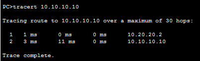
My question is when I am doing traceroute either from 10.10.10.10 or 10.20.20.20 they both are going through their associated interface vlan IPs. Are they not supposed to use the HSRP VIP instead of interface IP? Please explain it to me. Thank you so much.
Ah, yes, this is a very good question. I was too hasty to mention traceroute in my previous post. This output is correct. Cisco states in its documentation that when using traceroute with HSRP, you will always get the actual and not the virtual IP in the output:
Q. Which IP address must be seen when a reply is received for traceroute?
A. When a reply for traceroute is received from a hop that runs HSRP, the reply must contain the active physical IP address and not the virtual ip address. If there is an asymmetric routing in the network due to which standby router IP address is seen in the reply for the traceroute.
Taken from https://www.cisco.com/c/en/us/support/docs/ip/hot-standby-router-protocol-hsrp/9281-3.html#tr
Having said that, my statements in my previous post should read:
Strictly speaking, asymmetric routing is when the return path is different than the incoming path, that is, when routing takes place via different routers. In such a case, the path that is taken according to the next hop router addresses used should give you different paths. In the case described above, it’s not strictly asymmetric routing because the next hop router addresses used will give you the same path for both incoming and outgoing packets. The packet does pass through physically different hardware, but the two HSRP routers must be considered as one routing entity.
I have a question for this command : switchport trunk encapsulation negotiate
On CCNP SWITCH i read :
" The encapsulation is negotiated to select either ISL or IEEE 802.1q, whitchever both ends of the trunk support. If both ends support both types, ISL is favored"
But ISL (CISCO -proprietary) is a dead protocol no ?
Why this defaut command prefer ISL ??
ISL is Cisco proprietary and in general dot1q is preferred. However, there are some default configurations and remnants of legacy technologies left over in Cisco IOS functionality. Another example is the VLAN 1002-1005 which are reserved for token ring and FDDI technologies. These are rarely used but are still there because the legacy coding has not been changed. I believe the default of the ISL protocol rather than the more popular dot1q is another such case.
I understood trunking and why it’s important. But I have questions in mind related to VLAN. First of all, how a switch adds VLAN information to its MAC address table. In other words, how does a switch know what is the vlan of a frame? Because, in the lecture, it is mentioned that the Ethernet frames generated by the hosts don’t carry any VLAN information.
Does the switch learn it from the VLAN and port configuration? Based on the port it is received the VLAN is decided? What if multiple VLANs present on one port?
Let’s use an example. Say PC1 is connected to SW1 on Fa0/1. Fa0/1 is configured to be on VLAN 10. When PC1 sends a frame out if its NIC card, it has no VLAN information. End devices do not know or care about VLANs, they just send their frames.
Now let’s look at a couple of cases:
Case 1: Frame exits Fa0/2 which is an access port on VLAN 10.
The switch will determine that this frame must exit Fa0/2. Fa0/2 is a port on VLAN 10 so it will exit this port and go to the destination. The frame will exit Fa0/2 without a VLAN tag.
Case 2: Frame exits Fa0/3 which is a trunk port where VLAN 10 is one of the allowed VLANs.
The switch will determine that this frame must exit Fa0/3. It KNOWS the frame belongs to VLAN 10 because it entered the switch on a port which is on VLAN 10, so when it sends it out the trunk it will add the VLAN tag 10. When the switch at the other end of the trunk receives it, it sees the tag as VLAN 10 and places it in this VLAN. The switch will only transmit the frame out of another access port on VLAN 10 or out of another trunk port where VLAN 10 is allowed.
So you see that the VLANs are meaningful ONLY when a frame is found within a switch or on a trunk. Once it exits an access port, the VLAN has no more meaning as the frame is stripped of any VLAN information.
Hello
If I have one switch which have Vlan 10. Ex. H1 is in Vlan 10 created normal ethernet frame and send it to H2 which is also in vlan 10 on the same switch. So did switch insert Tag to Ehthernet frame from H1 ?
A switch will add a tag to an Ethernet frame only when it exits a trunk port. Once it enters the trunk port on the other end of the link, the tag is removed. So tags exist on Ethernet frames only when they are traversing a trunk.
This is a good question because you can’t just plug in a monitoring computer to the trunk port, as no traffic will be sent to examine. A solution is to use SPAN to create a monitoring port that mirrors a trunk port. That way you can capture packets over the specific trunk that are duplicated on the SPAN destination port. You can find out more about SPAN at this lesson:
are vlan tags needed if we have a layer 3 switch with ip routing? I was doing a lab where I configured dhcp on a router and had a layer 3 switch in the middle. It was confusing that i didn’t need to tag the traffic from the router to the switch because there where two vlans on the switch with two access ports one in each vlan.
Tags are always used for frames that are traversing a trunk. Specifically, when a frame on, say, VLAN 10 is sent over a trunk, when the frame exits the trunk interface of the switch, a tag is added to the header with VLAN 10. Once the frame reaches the other side of the trunk, the trunk interface of that switch reads the tag, removes it and places it in the appropriate VLAN. So tags are only added when a frame egresses a trunk port and removed when it ingresses the trunk port at the other end of the trunk.
This is the case regardless of whether your switch is layer 2 or layer 3.
Two 2960 switches connected to each other but the interfaces are not configured with any trunk or encapsulation commands and One of the two switches has been replaced with 3750 but still the interfaces are not configured with commands like " switchport mode trunk or switchport trunk encapsulation dot1q." This created broadcast storms to other network devices and made stop forwarding traffic. I guess 2960 switch supports only dot1q encapsulation by default where 3750 switch supports dot1q and ISL. So in this situation what must have happened between the switches to generate broadcast storms ? I’m looking for real root cause of the scenario.
If the ports on the two switches have no configurations on them, then by default both ports are access ports. This means that there is no encapsulation configured on them so the issue has nothing to do with dot1q or ISL or tagging at all. If you get broadcast storms, the thing I would examine next is to see if you are inadvertently creating a layer 2 loop with the connection. Check that there is no physical loop on the VLAN that is configured on the ports, and also check to see that STP is working correctly.