Hello LAZ,
Thank you for the response.
Regards,
Harshavardhan
Hello LAZ,
Thank you for the response.
Regards,
Harshavardhan
Hello, In the video of introduction to 802.1q. Is it layer 2 or layer 3 switches that Rene referes to in the video? Should it matter if it is layer 2 or layer 3 switches. It would work the same way anyway? Regards Lars.
Hello Lars
For the 802.1Q feature, you’re right, it doesn’t matter if you are using an L2 or L3 switch. The 802.1Q feature is a Layer 2 feature so both types of switches support it.
I hope this has been helpful!
Laz
is there any show command to check how many tagged/untagged packets the switch has forwarded on its interface . if not Is there any way to find out without using any traffic capture tools . Please suggest .
Hello Sameer
Simply using show commands will be difficult to give you this information. The only way that I can think of is to configure the port so that it tags the native VLAN so that any untagged frames will simply be dropped. You can then examine the dropped frames counter to see how many frames have been dropped, and the total number of packets that have been sent to see the tagged frames. But this is not very accurate, as frames can be dropped for other reasons as well. This might give you a ballpark figure, but by no means is it ideal.
Another option that comes to mind is using MAC ACLs, but after further research, they don’t have an option on filtering (or monitoring) based on VLAN tag.
The only other option is to either use SNMP and find a MIB that will give you that info, or use a packet capture tool. I can’t think of something else at this time…
I hope this has been helpful!
Laz
Thanks Laz for this info , Ok then i will look for snmp objects which can give me the exact count .
Hi Laz ,
I was trying to download all snmp v2/v1 mib files . following link at https://www.cisco.com/c/en/us/support/docs/ip/simple-network-management-protocol-snmp/9226-mibs-9226.html#q2
Q. How do I retrieve Cisco MIBs with anonymous FTP?
A. Follow these steps:

    Use an FTP client program to go to ftp.cisco.com.
    Log in with anonymous as the user name and your email address as the password.
    Issue the cd /pub/mibs command, to change directories to /pub/mibs/. All version 1 MIBs are in the v1 directory and all version 2 MIBs are in the v2 directory.
    Go to the appropriate v1 or v2 directory, to retrieve the MIB for which you are looking.

If you encounter any problems, try to log in with a minus sign (-) as the first character of your password. This turns off a feature that might be confusing your FTP client program.

To download files from CCO, you must use a passive-mode-capable FTP client. Contact your systems administrator to obtain one.

Send any questions, comments, or problem reports about FTP-related issues to Cisco.com Feedback.
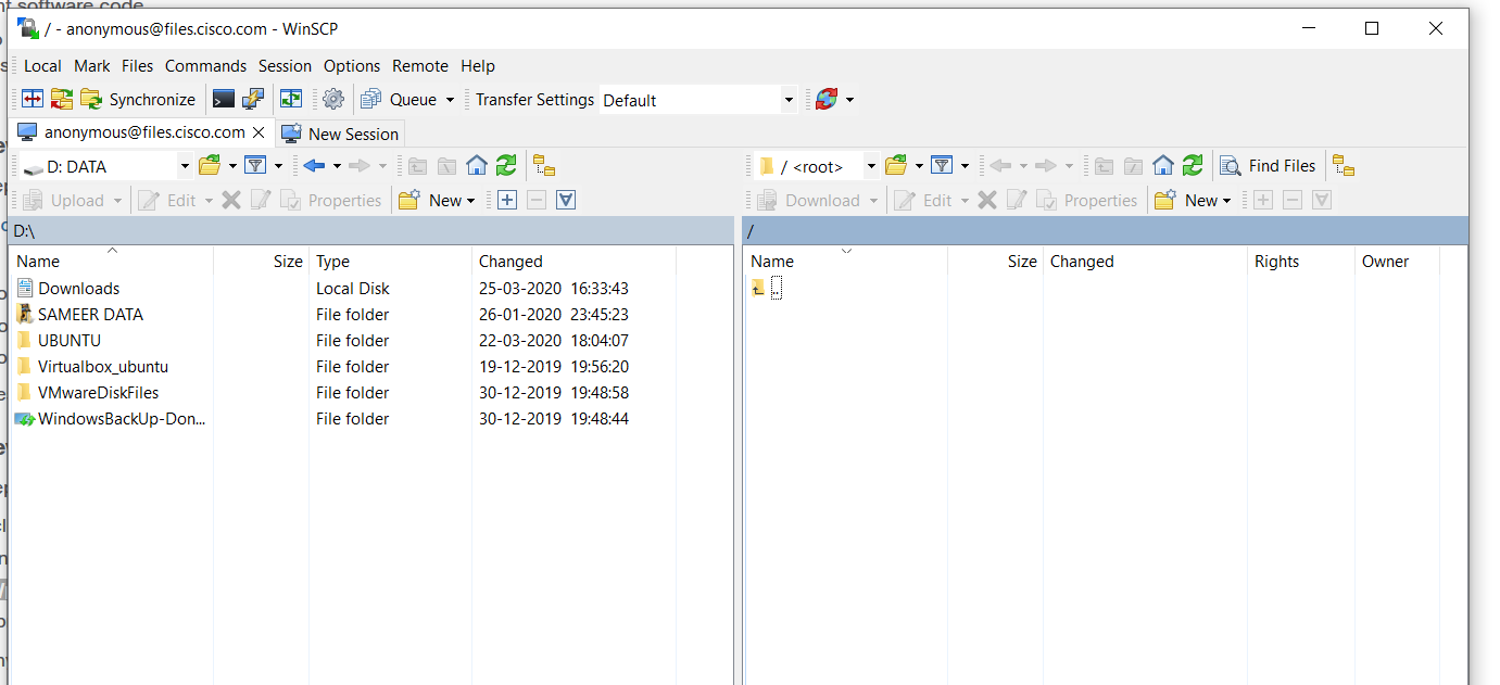
I am using winscp client and using my cisco credentials , tls/ssl encryption with port number 990 , i am able to connect “files.cisco.com” (but ftp.cisco.com unable to connect) . But i am unable see the contents /pub/mibs/ directory . Can you please let me know where can i download mib files .
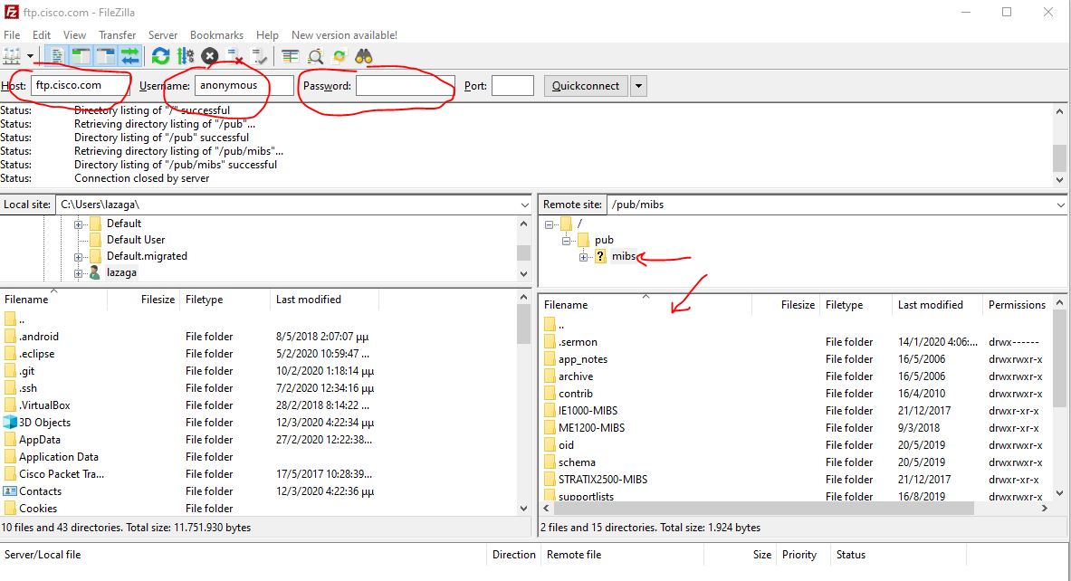
Hello Sameer
I was able to successfully log in to ftp.cisco.com using FileZilla and using anonymous as the username and no password. I was able to get a file structure under /pub/mibs as shown below:
I’m not familiar with the files.cisco.com. In any case, try again and do some troubleshooting to see where the problem is.
The related document also states that:
If you encounter any problems, try to log in with a minus sign (-) as the first character of your password. This turns off a feature that might be confusing your FTP client program.
To download files from CCO, you must use a passive-mode-capable FTP client.
See if one of those is the issue that you are facing.
I hope this has been helpful!
Laz
I had mostly used vtp like this on boson lab simulator . boson says that ,802.1q works only on old switches ?
Switch trunk encapsulation dot 1q
Switch port mode trunk
Hello Abdul
802.1Q is the standard that defines how VLAN traffic is encapsulated over trunks. This is the way that virtually all network device manufacturers implement trunks on their devices. Now before 802.1Q was established as an industry standard, Cisco also used their own proprietary encapsulation protocol called Inter-Switch Link (ISL). ISL has been phased out of most of Cisco’s newer equipment, but in older equipment, you had the choice of which encapsulation method to use. This was done with the command that you state in your post. Specifically:
SW1(config-if)#switchport trunk encapsulation ?
  dot1q      Interface uses only 802.1q trunking encapsulation when trunking
  isl        Interface uses only ISL trunking encapsulation when trunking
  negotiate  Device will negotiate trunking encapsulation with peer on interface
In newer switches, you don’t have this option, because there is only one choice, which is 802.1q. So the command is not available in newer switches not because it is no longer supported, but because it is now the only option.
I hope this has been helpful!
Laz
Hi everyone;
I am using PACKET TRACERT for LAB. i used switch model 2960 to make my topology. But i want to configure one interface by puting the one en trunk with isl encapsulation, i réalise that the commande: SWITCHPORT TRUNK ENCAPSULATION doesn’t exist on the switch. I can type switchport trunk but not SWITCHPORT TRUNK ENCAPSULATION. That refuse.
I don’t know how to fix this problem. anyone has one idea for me?
Thank in advance for answer. Thank
Hello Daoud
Most modern switches no longer support ISL, and this is also evident in the switches made available in Packet Tracer. These switches are set to use dot1q encapsulation only, and so the command is not made available. Some IOS versions and platforms do support the command but don’t actually have the ISL option there.
If you go into an older device, or an older version of Packet Tracer, you will have models and ISO versions that support ISL.
I hope this has been helpful!
Laz
Hello Lagapides;
Thanks for your feedback. I do understand why I can’t use the command SWITCHPORT TRUNK ENCAPSULATION. So that means the ISL will disappear? But I also realized that other commands don’t work on the switch 2960 or 2950 even the level3 switch too.
For example, I can’t use the command: DEBUG SPANNING-TREE EVENTS and many others. So how can we do the labs? I use the moderne of switch which is recommended in the course by René MOLENAAR but some commands don’t work and we can’t very well practise the labs? How can we do? Do you have any other tips for us?
Thanks in advance for your help
Hello Daoud
The truth is that many different platforms and IOS versions have various feature sets and capabilities, and there is no guarantee that any one platform will be able to provide you with everything you need. The recommendations found in this site, and those offered by Cisco as well are simply guidelines that help you to get as much as possible out of the labs that you create.
The various options that are suggested to you include emulators like GNS3, EVE-NG, and VIRL and CML. You can also use real devices, but once you obtain them, they are not modifiable. They are better for experience but not as flexible as emulators.
The best is to maintain a combination of various tools, and when you need something that you are unable to achieve, see how you can obtain it, either by using another emulator, obtaining another IOS, or another physical device. Over time, you will accumulate a lab that will be able to support most of the things you want to do…
I hope this has been helpful!
Laz
Hi Laz/Rene,
This might be unrelated to this topic, but can you kindly explain why the no of Tx packets != no of Rx packets on a default interface.
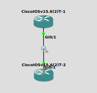
I have a simple topology as shown in the picture
Router1#sh interfaces gigabitEthernet 0/1 stats
GigabitEthernet0/1
          Switching path    Pkts In   Chars In   Pkts Out  Chars Out
               Processor          9       3069        122      12412

Router2#sh interfaces gigabitEthernet 0/1 stats
GigabitEthernet0/1
          Switching path    Pkts In   Chars In   Pkts Out  Chars Out
               Processor          9       3069        122      12412
So from my understanding, if Router1 and Router2 are connected to each other the number of packets transmitted by Router1 should be equal to the number of packets received by Router2. But as you have seen from the above stats I pasted the numbers are way off. Observed the same thing on Juniper as well.
Can you please explain this behaviour?
Thanks and regards,
Teja
Hello Teja
Hmm, that does seem strange! You are indeed correct that the Tx of one switch should be the same as the Rx of the other, and visa versa. It’s also interesting that not only are the values way off for each direction, but the Chars In is exactly the same on both switches as is the Pkts Out.
This cannot be a coincidence, so I assume that the same value is being measured in each case. Are you sure that the correct interfaces are being checked? Are you sure the connections are indeed as they appear in the diagram above? Also, how are you emulating this, in GNS3?
You are correct that what is appearing is incorrect, but maybe answering some of these questions will help in discovering the reason for this strange behaviour.
I hope this has been helpful!
Laz
is there any way i can communicate between 2 host who are different VLAN in the same or different switch ??
Hello Narad
In order for two hosts on two different VLANs to communicate, there must be a router involved.
Hosts on a specific VLAN will all have an IP address in the same subnet. This means that these hosts can reach each other directly. However, if you want to reach a host in a different VLAN, and thus in a different subnet, a host must direct its traffic to the default gateway. This will allow the packets to be routed to a different VLAN.
This can either take place using inter-VLAN routing, which is a feature of Layer 3 switches, or using an external router such as in the case of router on a stick.
Both of these cases can be implemented whether the hosts are connected on the same switch or on different switches. But in each case, a layer 3 routing device must be used in order to route traffic from one VLAN to another.
I hope this has been helpful!
Laz
Hello, everyone.
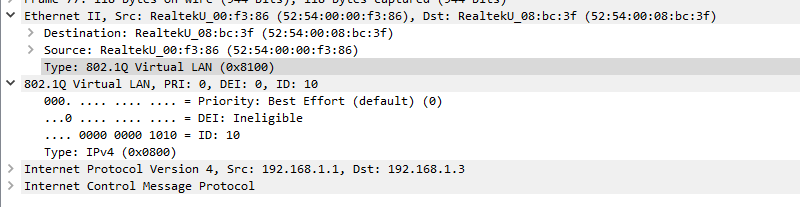
The Dot1q header is inserted between the Source MAC and the Type field of the Ethernet header. However, Wireshark happens to display it differently.
It looks like the Dot1q tag is inserted between the IP header and the Ethernet header. This, however, isn’t correct, right? Or how should I read what Wireshark captured here?
Thank you.
David.
Hello David
You’re correct in your understanding of where the dot1q tag is inserted. The 802.1Q tag is indeed inserted between the Source MAC and the Type/Length fields of the Ethernet frame.
However, the way Wireshark displays the packet can be a bit misleading. Wireshark is designed to make it easier for us to analyze the packet, so it reorders the fields to group them together in a way that makes sense from a protocol analysis point of view. This is why it appears as though the Dot1q tag is inserted between the IP header and the Ethernet header.
So, no, it’s not technically correct that the dot1q tag is inserted between the IP header and the Ethernet header. But it’s displayed that way in Wireshark for ease of analysis.
I hope this has been helpful!
Laz