Hi Rene
In case SW3 is not only running dot1q-tunneling service. Let say S3 is our core switch and S1 and S2 are our distribution switch which carry many vlan service which is not dot1q-tunnel, How ever we have new service dot1q-tunnel between S1 and S2 as your configuration we change to change
switchport trunk encapsulation dot1q on interface between S1 to S3 and between S3 to S2. So will it effect another normal vlan that running on this port ?
Hope i got the answer thank you
Hello Heng
The QinQ tunnel is actually configured on the Fa0/1 interface of SW1 and the Fa0/2 interface of SW2. So all tagged frames of multiple internal (to R1) VLANs entering Fa0/1 of SW1 will have an external tag of 123 and will be transported from SW1 to SW2 to SW3. If you want to have additional VLANs transported over the SW1 to SW2 trunk, and the SW2 to SW3 trunk, you can do that. The QinQ VLAN is treated just like any other VLAN within the core network.
The only configuration that cannot be changed is the access switchport configured on SW1 and SW2. Those ports can only carry the 123 QinQ VLAN and no additional VLANs.
I hope this has been helpful!
Laz
So why we need to apply this command on the upstream port between s1 s3 and s2 ?
SW3(config-if)#switchport trunk encapsulation dot1q
Hello Heng
802.1q encapsulation is the normal trunk encapsulation used on all Cisco switches. Older devices had the choice of using ISL as an alternative, but newer devices don’t have this option, only 802.1q is available. The commands are entered here only for completeness, as the 802.1q trunk encapsulation is the default on all Cisco devices.
Note here that 802.1q is not the same as QinQ. 802.1q is just the regular tagging you use in all trunks. Q-in-Q as a feature is actually defined officially in 802.1ad.
So the dot1q encapsulation command is not specific to a QinQ configuration, but is the implementation of trunking in general.
The QinQ specific configuration is applied only the Fa0/1 interface of SW1 and the Fa0/2 interface of SW2.
I hope this has been helpful!
Laz
Hi René. Quick Question: when creating the sub-interfaces, my Cisco 1841 router offers me 4 choices for encapsulation: dot1Q IEEE 802.1Q Virtual LAN
what is the difference between “dot1Q” and “802.1Q” ???
we are actually trying to implement this on our network using Juniper switches. I love the idea of studying both in parrallel.
Michel
1 Like
Hello Michel
I think you may have misread the output. What you have mentioned as dot1Q IEEE 802.1Q Virtual LAN is a single choice which simply includes the description of that choice. Going into another router, I did the following:
R1(config-subif)#encapsulation ?
  dot1Q            IEEE 802.1Q Virtual LAN
  isl              Inter Switch Link - Virtual LAN encapsulation
  priority-tagged  Priority-tagged (VLAN 0)
You can see here that there are three choices in the specific device. The first one, is the same one that is supported in the 1841. The command is actually dot1Q and the description of that command is IEEE 802.1Q Virtual LAN.
If I am not mistaken, the 1841 only supports 802.1Q. Other choices include ISL, which is an older and largely obsolete Cisco proprietary trunking protocol, while priority-tagged, is outside the scope of the lesson, but you can find out more about it here.
So to answer your question directly, dot1Q is the keyword that enables the 802.1Q encapsulation for the subinterfaces of the router.
I hope this has been helpful!
Laz
1 Like
Ah ah ah : kind of ironic to have such an exemple of tunnel vision while studying tunneling.
My brain saw various options and stuck to it.
Thanks for straightening it.
Michel
1 Like


Hi Rene/Laz,
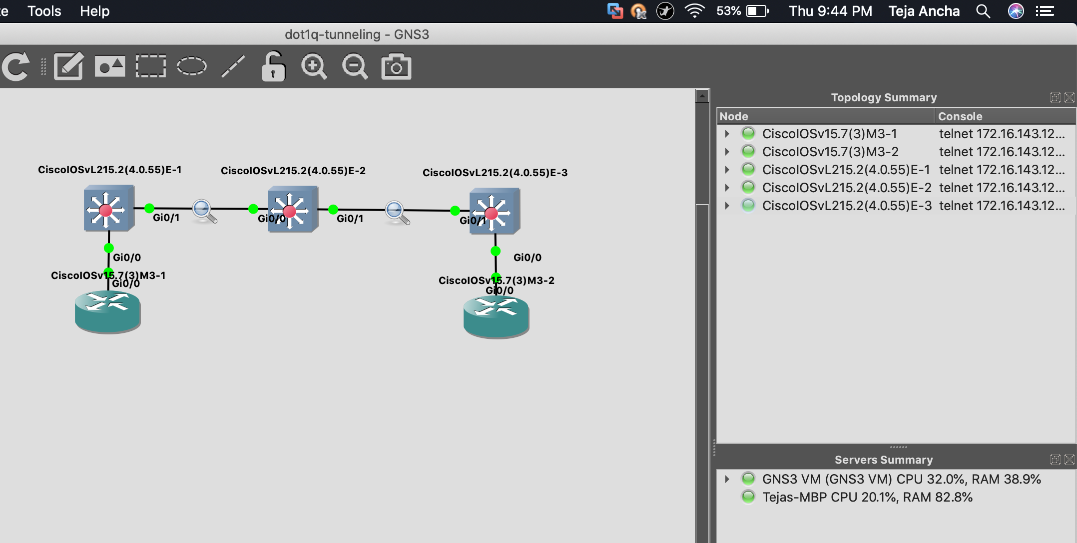
I tried replicating the same on my GNS3 setup, however I am not able to ping from either sides. I have turn on debug to check the issue, it says that the encapsulation has failed. Can you kindly explain what is the work around, what is causing the encapsulation to fail?
Thanks and Regards,
Teja
Hello Teja
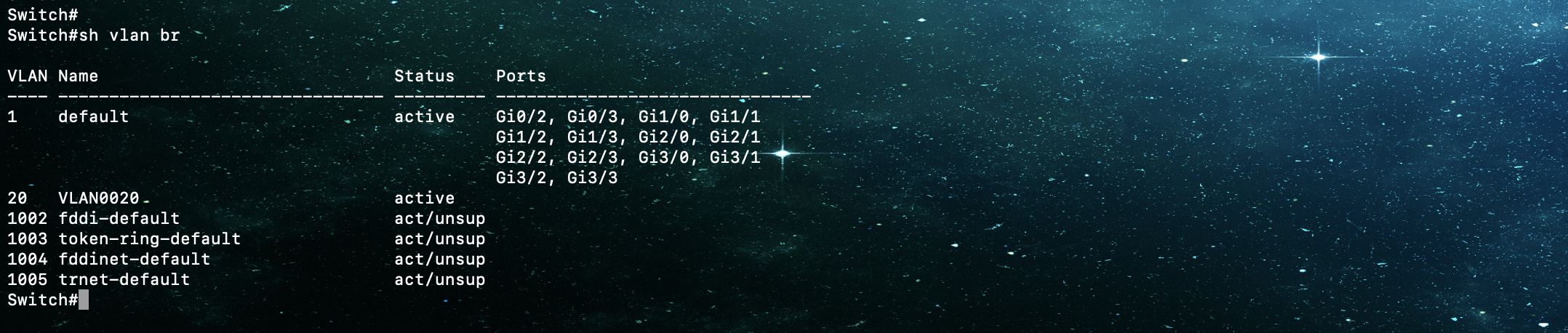
Looking at the output you show, I’m not sure which output belongs to which switch since all switches have the same name. But I think I figured it out. Here are a couple of things to keep in mind.
The encapsulation error is on the GigabitEthernet0/0.1 subinterface of the router, so the problem is not QinQ, but in the router-on-a-stick configuration. Check your encapsulation configuration on the router end of the link including the VLAN tag ID. Keep in mind that there is a bug involved with this for older IOS versions, so if your config is good, it may be the bug.
Other than that, your configuration on the switches looks good, as long as you are including VLAN 20 across all switches.
I hope this has been helpful!
Laz
1 Like
Hi Laz,
Thank you, I tried the same topology with a different IOS version and it seems to work fine. As you suggested it might because of the bug in the older releases.
Best Regards,
Teja
1 Like
Hi,
Is possible that a carrier provide us an access port in their q-in-q circuit?
Thanks
Hello Giovanni
Yes, typically, a provider that offers QinQ will provide you with an L2 access port to which you connect your equipment. You configure your port as a trunk port and send all your VLANs over that connection. The provider will offer L2 access ports at all of your remote locations, and you configure all of your equipment in the same manner, resulting in all of your internal VLANs being shared among your own sites.
The provider will use a particular VLAN for you as a subscriber, through which all of your internal VLANs will be sent. This VLAN, and the related QinQ configuration on the part of the provider is completely invisible to you as a customer.
I hope this has been helpful!
Laz
OK, but how the customer can configure a trunk port if the other provider switch is an access port, and what about BPDUs? exist the possibility that a BPDU sent to or by the provider switch can influence the L2 network of the customer..
( at work a customer asked me this thing and I was not so sure about that..)
@anchadharaniteja can you tell me how did you change the background of the terminal..this is awsome ![]()
Thanks
1 Like
Hi @obertigiovannicesare,
Open terminal on your Mac, on the top left corner you will see options  in this image in the place of finder you will see option called Terminal, click on it and you will get a drop down menu, click on preferences. Up on clicking preferences it will take you to this window.

1 Like
Hello Giovanni
That’s the definition of QinQ. The provider offers an access port on a single VLAN, while the customer uses a trunk port, sending multiple VLANs. The key command in all of this is the third command in the following sequence on the provider’s interface to the customer:
SW1(config)#interface fastEthernet 0/1
SW1(config-if)#switchport access vlan 123
SW1(config-if)#switchport mode dot1q-tunnel
This third command tells the switch to accept all tagged frames and tunnel them through a single VLAN (123) providing a second tag within the provider’s network.
No, BPDUs will not affect the customer. This is because we have created a tunnel. The internal (customer) traffic does not know of or conceive of the external (provider’s) traffic. If you were to do a CDP neighbor lookup on the customer’s device, they will not see any of the provider’s equipment, even if it is Cisco, because the CDP traffic is tunnelled through the QinQ tunnel. So from the point of view of the customer devices, they are directly connected to each other, and there is no provider network.
I hope this has been helpful!
Laz
Thanks a lot , I did a lot of lab about that, now I understood now.
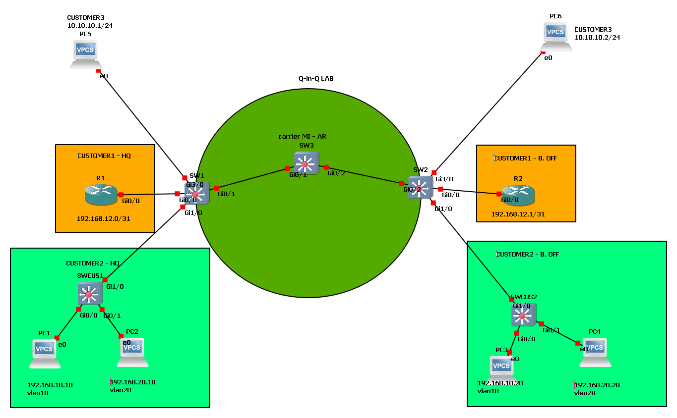
Another question(last I promise ![]() ) ..based on my lab…exist the possibility to put down the carrier ( green zone ) network , if I connect 2 sistes with another QinQ ciruit? (for example another connection between SWCUS1 and SWCUS2)
) ..based on my lab…exist the possibility to put down the carrier ( green zone ) network , if I connect 2 sistes with another QinQ ciruit? (for example another connection between SWCUS1 and SWCUS2)
p.s.
@anchadharaniteja thanks a lot but I use windows / linux, I not found this option but I will do more search ![]()
Hello Giovanni
If I understand correctly, you want to create a second QinQ connection between SWCUS1 and SWCUS2 via the ISP. You can indeed do this, and if you pass the same VLANs in the second QinQ tunnel, then STP will begin to function between the two switches for those VLANs, causing one of the links to be in a blocked state to avoid a L2 loop. Remember that the customer switches cannot perceive the ISP network, it’s as if you are connecting them directly.
I hope this has been helpful!
Laz
2 Likes
This is exactly what I needed to know.
Thanks
Maybe this has been asked before, but do you have any idea if Q-in-Q works in GNS3 with IOU-L2 or IOSv-L2? I am pretty sure at this point it is broken / unsupported , but a confirmation will be nice ![]()
Hello Ilev
I haven’t personally tried QinQ on GNS3, but according to this GNS3 post (as of September 2019), it seems that IOU-L2 and IOSv-L2 do not support QinQ. I’ve done some more research and found that some have actually achieved it with limited results. They are able to get the verification commands to work, but connectivity is not achieved.
I believe that this feature will eventually be available in the GNS3 images, but it may take some time yet. Keep an eye on the GNS3 forums to keep up to date on this…
I hope this has been helpful!
Laz