Hi
I had encountered the same issue with my lab, yes the traditional image not support Q-in-Q.
You should use a Cisco IOS Software, vios_l2 Software (vios_l2-ADVENTERPRISEK9-M), Experimental Version 15.2(20170321:233949).
Bye
Hi
I had encountered the same issue with my lab, yes the traditional image not support Q-in-Q.
You should use a Cisco IOS Software, vios_l2 Software (vios_l2-ADVENTERPRISEK9-M), Experimental Version 15.2(20170321:233949).
Bye
I was unable to get your wireshark capture results in your graphic above in the QinQ lesson. I placed the workstation port in vlan 123 but only get results below
Hello Donald
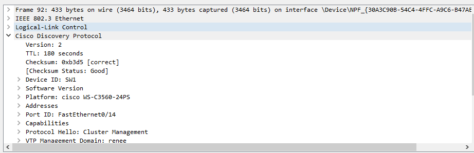
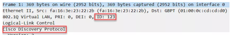
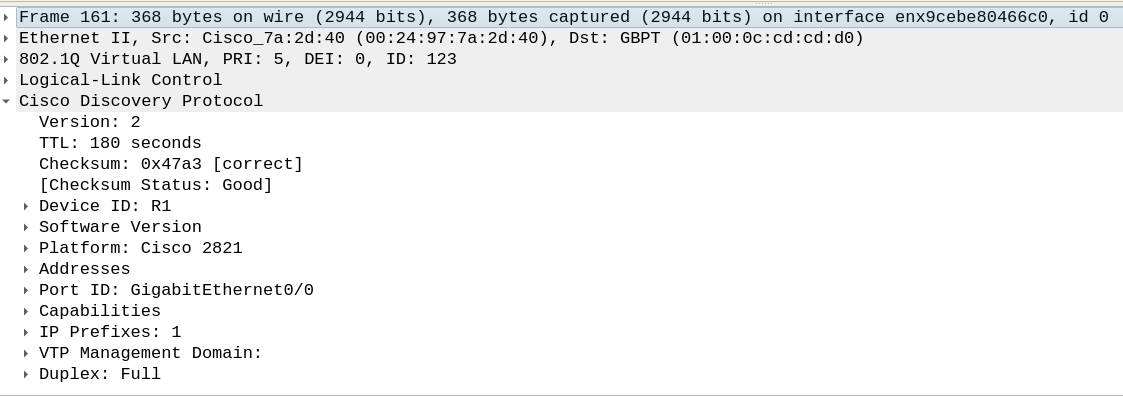
It seems that your wireshark capture is capturing CDP packets. These CDP packets will only see the “inside” VLAN which is 123. The devices that are exchanging CDP packets “think” that they are directly connected over that particular VLAN. This is the same as the first wireshark capture that Rene has in the lesson:
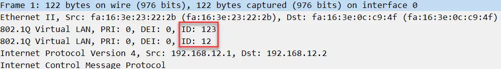
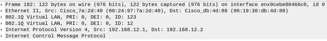
The wireshark capture where both the “inside” and “outside” VLAN tags appear is the wireshark capture for the ping that takes place from R1 to R2. In this wireshark capture, you will indeed see both tags as shown in the lesson. Keep in mind that this capture must take place at one of the switches, ideally SW3, in order to see both VLAN tags. Try capturing a ping at SW3 and see what results you get.
I hope this has been helpful!
Laz
Laz
I moved the host to SW3. Still not seeing the 8021Q tags in wireshark. Still experimenting with this. I’ll update post with new info if I find an answer before you see this.
Thanks
Hello Donald
What packets are you capturing? If you’re using real devices you’ll need to configure SPAN on SW3 to capture frames that are entering and exiting either Fa0/19 or Fa0/21 on SW3 so you can see the actual traffic between R1 and R2. If you’re using an emulator (like GNS3 or VIRL), it will be easier to capture such traffic, as you can specify the location of the capture you want to perform.
In any case, if you’re not seeing two tags, then either the interface in which you are capturing them is incorrect, or there is an issue with the QinQ configuration. Keep troubleshooting and let us know of your progress.
I hope this has been helpful!
Laz
Laz
I am capturing ICMP packets using real devices.
R1 - 2821 15.1(3)T4
R2 - 2600 12.2(12)b
R3 - 2821 15.1(3)T4
SW1 - 3560 12.2(55)SE6
SW2 - 3550 12.2(25)SEC
SW3 - 3560 12.2(55)SE6
physical connections - R1 → SW! → SW2->SW3->R3
Just have the positions of each SW2 and SW3 changed
so the 3560’s would be the tunnel devices
Wireshark capture device - Ubuntu laptop on SW2 with its port monitoring
Consoled in from Ubuntu desktop putty session to terminal server to access devices
I can attach QinQ commands from each device but R1 sees R3 as directly connected .
Pings from R1 (192.168.12.1) to R3 (192.168.12.2) are successful from desktop console putty session
Thanks
Hello Donald
Thanks for sharing that detail. Now based on your description, if you are capturing packets at the interfaces of SW2 (which is the center switch in your topology) you should be seeing two tags on the frames. If you are not seeing two tags, then something is wrong with the configuration.
Yes, that is correct, R1 should see R3 as directly connected. This would be the case if QinQ is correctly configured, or if QinQ is not configured at all and you simply have a normal L2 connection between all switches, so this is not a proof that the config is correct.
I suggest you do some troubleshooting on the configurations of QinQ on the three switches until you see those two VLAN tags on the frames captured at SW2.
I hope this has been helpful!
Laz
Laz
The issue was choosing the incorrect adapter for the wireshark capture.
Now I can see the tunneled CDP packets in wireshark showing R1 and R3
are directly connected neighbors.
Hello Donald
That’s good to hear, and thank you for sharing your solution!
As for your ping, that seems strange. The only thing you’re changing is the DF bit? What size of a ping are you sending? If it is successful it should appear in your Wireshark capture. I suggest you verify that the destination IP is correct and that the packet is indeed taking the correct path. Are you sure you’re getting an echo reply that says it is successful?
Take a look at those and let us know…
I hope this has been helpful!
Laz
Laz
I’ll verify the lab again and post an update tonight.
Thanks
Hello All,
I’m new to Cisco IOS; I came from 10 years of experience in networking protocols (OSPF-MPLS-BGP); I studied for Mikrotik certification and in the last years I used Mikrotik routers.
Right now I’m studying to choose between Cisco and Juniper routers, to add them to our network; I’m doing tests on EVE-NG; in the last days, I’m testing a CSR1000V with a smart license installed on it.
I’m testing for VLANs and q-in-q; the problem is that in the shell I didn’t find commands like this:
encapsulation dot1q 101 second-dot1q 1001
In my case, second-dot1q is not present in lists of commands.
Can someone help me; where is the error? should load a license in my virtual router?
Based on my experience maybe Juniper is easier because in Cisco there are different shells (IOS XE,XR, nx-os).
Any suggestion is appreciated.
Thank you so much in advance, Francesco.
Under the interface, do you already have an encapsulation dot1q 111 command already set? I ran into this on older versions. If so, you’ll just remove the command and re-add with encapsulation dot1q 123 second-dot1q 321.
Hello mattdover,
yes it work!
Thank you so much, Francesco.
Hello Laz,
“In either case, the fact that you are using QinQ doesn’t affect what solution you will use. From your perspective, you just have two trunks that connect your two sites. The ISP is doing all the QinQ stuff.”
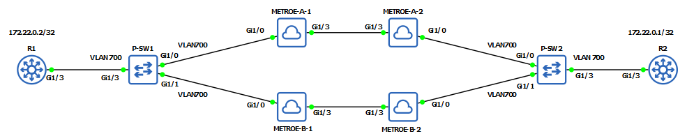
I’ve tried this on GNS3, the lab worked fine when the customer interfaces (P-SW-X) are configured with:
switchport mode access
swichport access vlan 700
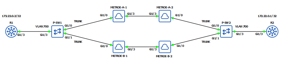
but when the customer interfaces (P-SW-X) are configured with:
switchport trunk encapsulation dot1q
switchport mode trunk
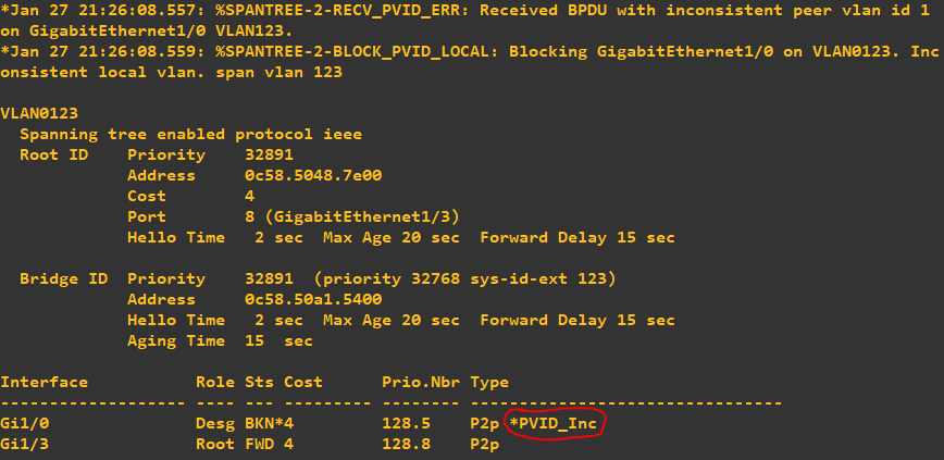
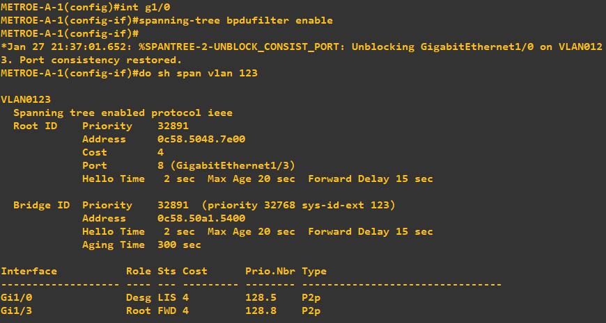
The provider switches METROE-A-1, METRO-E-A-2, METROE-B-1, METROE-B-2 G1/0 interfaces are blocked by spanning tree as it receives a BPDU from a different VLAN. Basically downing the METRO-E line that the customers availed.
We can bring up the port again by enabling the bpdu filter on provider interfaces facing the customers. Basically disabling spanning-tree on that interface. Example screenshot below:
My question is that is it realistic in the real-world that providers would configure spanning-tree bpdufilter enable on their end? Or is there another solution to this? Thank you!
Hello Alvis
If QinQ is configured correctly, then any control protocol data units, such as BPDUs, CDP, VTP and so on that are sent by customer equipment should not be detectable by the carrier equipment. Such data units should be tunneled and simply passed through the carrier network to be received by the customer equipment on the other end. This Cisco documentation describes it like so:
When protocol tunneling is enabled, Layer 2 protocols within each customer’s network are totally separate from those running within the service-provider network. Customer switches on different sites that send traffic through the service-provider network with 802.1Q tunneling achieve complete knowledge of the customer’s VLAN.
(The documentation may be for Nexus devices, but the logic is the same).
You must ensure that the ports of the provider network to which the customer equipment connects are correctly configured with the switchport mode dot1q-tunnel command. This will ensure that all control data units like BPDUs will not actually be seen by the carrier network. In actuality, these must be forwarded unaltered to reach the customer equipment on the other end, because, from the point of view of the customer equipment, the customer switches are directly connected, and there is no intervening infrastructure.
This is one of the fundamental characteristics of QinQ.
I hope this has been helpful!
Laz
Thanks Laz, understood it now.
Hello.
Shouldn’t the S-tag has the type - 0x88A8 ?
If not, could you elaborate on your answer ?
Thanks in advance.
Hello Vadim
Yes, you are correct, that the official IEEE 802.1ad specification of QinQ does indeed specify that an Ethertype of 0x88A8 should be used for the service provider tag. However, it seems that Cisco has chosen not to use this particular tag. Indeed other vendors like Juniper as well choose to keep the default 0x0800 tag there instead. Remember that this is just a label, and it is used to let devices know that there is a service provider tag there and should be interpreted as such. However, devices are still able to distinguish this even if this ethertype field is not changed.
This information is added by the provider network, so the provider network, so if all equipment within the provider is the same, they can all interpret this ethertype in the same way, so there is no real problem in functionality.
I’ve taken a look at some other cloudshark captures of QinQ on the Internet, such as the one linked below, and you can see that this is the case here as well:
This is an example of a standard that IEEE has put in place that some vendors simply choose not to abide by.
I hope this has been helpful!
Laz
Hi,
suppose the customer switch is inside the campus network, when I put switchport mode dot1q-tunnel how can I manage the customer switch if I want to make further changes on the customer switch ports in the future?
Hello Valerio
Typically in such a scenario, the configuration of customer switches is the responsibility of the customer. It is true that by issuing the switchport mode dot1q-tunnel command on SW1 and SW2 in the topology, you would no longer have access to the “inner” VLANs from the ISP network. But that’s OK, because typically a telco will not be responsible for this configuration.
The point is that the customer switches will have no special configuration, as they will simply be connected on each end, and will “believe” that they are directly connected over a trunk, sending and receiving data on all their allowed VLANs. If you do a show cdp neighbors, the switch actually believes it is directly connected to the one on the other end.
As a customer, the ISP would simply give you an ethernet port and say that you can go ahead and send your trunk through there. What happens in the Q-in-Q config of the ISP is no concern of the customer. The demarcation between customer and ISP is located at the physical circuit delivered by the ISP to the customer.
I hope this has been helpful!
Laz