What you are proposing configures a second VC across the same two PEs on the same physical interfaces that connect to HQ and Branch. If this was to be done for a second customer, it would have to terminate on different interfaces and use a different VC label (as you have already done in your example).
Hi Laz
Thanks for the reply. To clarify, my sinario is the second customer uses the same LSP(PE1-P-PE2) but physical Attachment circuit(AC) should be different from first customer. It is natural, isn’t it ? In that case, different AC mapped to different VC label(Demux field). Another sinario: Same customer, same physical AC but different 2’nd virtual connection(DLCI, VPI/VCI, VLAN) should also be mapped to different VC label. Is it right ?
Yes, that is correct. That is indeed the way it should be done.
Actually, if you were to create a second xconnect configuration on the same interface, it will actually overwrite the previous one. So you cannot configure two separate xconnect configurations on the same physical interface, even if you use a different VC label.
In general, these terms can be used interchangeably, but have slightly different meanings. A pseudowire is the feature used by Cisco devices to provide end-to-end point-to-point layer 2 services. A virtual circuit is a specific point-to-point circuit created using the pseudowire feature. Each such circuit is signified by a Virtual Circuit ID that shows up in the output of the show mpls l2 vc command.
So pseudowire is the feature, while virtual circuit is the specific point-to-point virtual link that is created in each case.
Even so, the terms are often used interchangeably and each time they are used, they should be taken within context to determine the actual meaning that is being expressed.
You may find this Cisco documentation that further describes the concepts of pseduowire.
HI Rene,
Did you manage to write something on the VPLS and HVPLS topics?
Also I am copying the configuration mentioned in this page , but my VCs are not coming up. PLease tell me the reason
PE2#show mpls l2transport vc

Local intf     Local circuit              Dest address    VC ID      Status
-------------  -------------------------- --------------- ---------- ----------
Fa0/1          Ethernet                   1.1.1.1         13         ADMIN DOWN
Rene has some high level info about VPLS in the following lesson, but nothing yet that includes configurations for this feature:
As for your config, there are various things that may cause a VC not coming up, but in your particular case, the Status is ADMIN DOWN. This indicates, as this Cisco Command Reference confirms, that “the VC was disabled by a user”. This could mean a shutdown interface, or no xconnect configuration on the other end. Review your config, and reissue the command with the detail keyword at the end to see the reason for which it is down.
I will Try to bring the configuration up again and let you know.
I have one more question..Like when we talk about MPLS L2 VPN like VPLS/VPWS we say that forwarding happens using mac addresses in these technologies , So Can you please explain How the mac -learnings happen in case of VPLS and VPWS and How we can see the mac-address table in case of VPLS and VPWS.
MAC address learning over a VPLS circuit involves the use of Type Length Value (TLV) encoding found within the LDP messages. However, the end devices that use such a connection don’t actually see any of this. They simply use the flood and learn method of MAC address learning as they normally would, so there is no VPLS-specific command that will show you MACs.
This is helpful , But I am not getting as how VPLS and VPWS learns mac addresses the same way L2 switch learns it , because there is no device connected directly with the PE on the NNI side. Also where does the VPLS PE router stores all these information of mac learned. Can you please explain in an elaborative way ?
Also Just want to know if there is mac learning happens in case of VPWS or not?
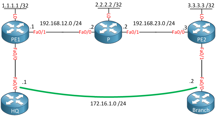
Now imagine that the HQ and Branch devices are switches. They will, both together, create a single broadcast domain/network segment with a subnet of 172.16.1.0/24. As far as those devices are concerned, their Fa0/0 interfaces are directly connected. They know nothing of the intervening network infrastructure, due to the creation of the VPLS. So from the point of view of these switches, they learn the MAC addresses “in the normal way”.
Now how do those MAC addresses get from HQ to Branch and visa versa? Well, the VPLS circuit that is created between the PE routers is negotiated and maintained with the exchange of the MPLS label switching. This mechanism includes TLV encoding within the LDP messages that carry the source and destination MAC addresses of individual hosts on each switch. When the HQ and Branch switches receive those frames, they simply populate their MAC address tables accordingly. MAC information is not maintained by the VPLS circuit, but is simply provided to the switches on each end.
If you want to learn more details about this, you can always do a search for “VPLS MAC address learning” in your favourite search engine and you should find some detailed and informative articles on the subject.
Concerning VPWS, MAC addressing is not exchanged. This is because VPWS, unlike VPLS, is a point to point service which means MAC addressing, or any Layer 2 addressing is not possible and not necessary.
I need documentation about connection xDSL for example (between CE and PE)
I want to learn how we configure our PE with DSLAMs and DSLAMs with our CE.
In the other case, how we configure equipment of transmission if we have FTTH link…
I’m technical support L2 at ISP and our network is special for entreprises.
My big problem => I want to learn how I can manage all of network HQ with other branchs (L2TP link, TAG Q in Q) deployment of MPLS L3 VPN, MPLS LAN to LAN… but I can’t find what I need…for this reason I’m not happy.
Keep in mind that MPLS is a technology that is often referred to as a Layer 2.5 technology since it sits somewhere between the data link layer and the network layer. This means that as a technology, MPLS can run over any L2 infrastructure, including xDSL, FTTH, Metro Ethernet, or wireless. There is no specialized configuration necessary for MPLS to run over such infrastructure.
You can take a look at the various lessons available within the MPLS course shown below:
If you have more specific questions about particular implementations or examples, please feel free to share them, and we’ll do our best to help you out.
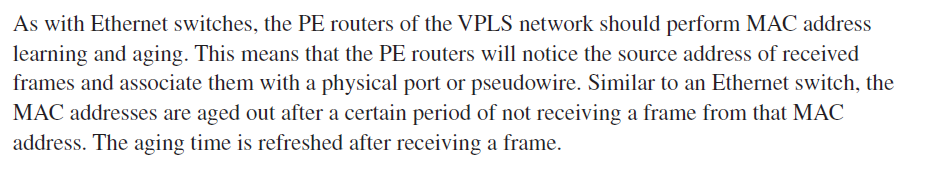
As you said that MAC information is not maintained by the VPLS circuit, This is what I found in one of the CISCO book for MPLS fundamentals. Can you please explain the below .
In my post above, I used an example of an Ethernet switch. In such a case, the switches will maintain a MAC address table, where MAC addresses correspond to specific ports of the switch.
In the case of a router, and in the case of the routers in the example in this lesson, the ARP protocol is being used. Using ARP, Layer 2 MAC addresses are mapped to layer 3 IP addresses. Note here that in the lesson, the two routers are using Layer 3 interfaces, with separate IP addresses.
Now the Cisco documentation you shared seems to be talking about an additional feature called pseudowire. This enables a router (layer 3) to create what is known as a bridge domain. This is essentially a Layer 2 switch operating on particular layer 3 interfaces of the router. This is why the text you shared is comparing the behaviour of switch MAC address tables, with a similar function of a router using pseudowire. You can learn more about how Pesudowire and VPLS and how these features work together at the following Cisco documentation:
If you would like to find out some more information about these and their differences, as well as how to configure them, take a look at some of these links:
To find out more about Virtual Forwarding Instances, including configuration take a look at this:
If you have more specific questions, please share more details about your topology and the related issues that you are facing, so that we can help you more specifically.