Cisco devices allow you to configure BFD at either a global level, or at an interface level. However, BFD configuration is generally linked with the interface and not with individual routes. Therefore, while you can create multiple static routes to the same next-hop IP, each with their own metrics, you would not typically configure different BFD intervals for each of those routes if they are using the same outgoing interface.
The ASR in your case is not “happy” with the different BFD intervals for two different routes that have the same next hop IP. This is seen in the error message below:
!!% 'ip-static' detected the 'warning' condition 'Nexthop is already configured with different interval or multiplier or multihop'
Although the commands were accepted, the error message does state that the running config and the operational state will indeed be inconsistent. So whether you commit them together or separately, the operational state will remain the same, the error messages are simply different.
I hope this has been helpful!
Laz
To implement diverse BFD intervals for the same next-hop IP, you’d likely need to utilize different outgoing interfaces, each configured with its respective BFD interval.
In any case, it’s important to consider that setting a different BFD interval per route to the same next hop might not be the best practice due to additional complexities and potential for configuration errors. It’s generally more advisable to apply a uniform BFD configuration to all routes to the same next hop, thereby simplifying troubleshooting and network operations.
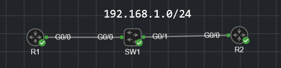
For below scenario, where DC-GW1 is the ASR9K using BE10 to reach Telco Cloud A.
Can we have setup here in this topology we can create two outgoing interface to create two different static route with different BFD minimal-interval value to reach Telco Cloud A?
As @lagapidis mentioned, the way BFD works is that you configure this on an interface level. Static routes, or routing protocols like OSPF, EIGRP, BGP, and IS-IS can use BFD for faster failover.
You would configure BFD once for your BE10 interface. If you have another interface between DC-GW1 and the Telco, you can configure BFD for this interface as well.
For these two interfaces, you can use different BFD intervals if needed.
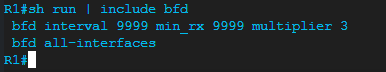
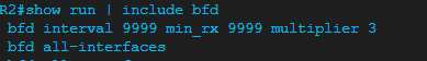
Doesn’t this basically mean that the routers should send BFD packets every 9.9 seconds, expect packets every 9.9 seconds and tear down the neighborship after 29.7 seconds?
If so, for some reason, this isn’t working as intended. The routers are constantly sending BFD messages between eachother way more often than just 9.9 seconds.
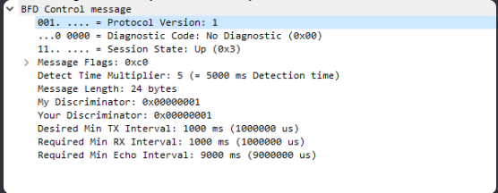
Hmm that is strange. The first thing I’d like to address is the fact that in the Wireshark capture, your multiplier is 5, and your Tx and Rx intervals are set to 1000 ms, and the Echo Interval is 9000 ms. Those values are different from what you set up in the two routers.
I don’t have an answer for your concerning why these are different, however, I do have some information bout how BFD operates that may shed some light on the discrepancies seen. First of all, looking at RFC 5880 that describes BFD, we see that:
Timers are negotiated - BFD will negotiate timers based on what is supported. Now you put in a value of 9999 for the interval, and this appears as 9000 in the capture. It could be that the platform may accept such a value in the command, but may default to a maximum value that the platform supports. This may be IOS specific.
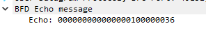
The control packets are the ones that would adhere to your interval and min_rx settings. In Echo Mode, however, BFD will send echo packets at a more frequent rate (usually on the order of milliseconds). The intention here is for these echo packets to be “echoed” back by the recipient. The missed echo packets don’t count against the multiplier, but it’s a means to verify the forwarding path without putting the additional load of control mode packet processing on the control plane.
When viewing the actual frequency of packets sent, the RFC says that it will differ from the set values by up to 25% based on jitter values and on a level of randomness introduced into the control packets to prevent self-syncrhonization.
The RFC also states that some of the timers must be initialized to 1 second (i.e. 1000 ms) before being changed and negotiated.
I suggest you take a look at the configuration of your routers using the show bfd neighbors details command to see what values are actually negotiated and used. Once that’s done, take a look at the steam of BFD packets several dozen seconds into the exchange to see if the values of these timers have changed, and to see if the frequency of their transmission has steadied. Please take a look at these and let us know what you find.
Is it mandatory that we need to enable BFD on interfaces along with any protocol.
For example, can i don’t enable BFD on interfaces and just enable under BGP neighbors’ statement?
The configuration of BFD parameters on the interface as well as on the routing protocol are necessary in order for BFD to function correctly.
The BFD configuration on the interfaces is not linked with any particular routing protocol. By issuing the bfd command on the interface, you are simply starting the BFD process, and you are setting the parameters (interval, min_rx, multiplier etc) with which BFD will communicate with the BFD entity on the other end of the link.
Once the BFD process is up and running, there are no entries created in the adjacency database yet, and no BFD control packets are sent or received yet. The adjacency creation takes place only when you configure BFD support for a particular routing protocol. That’s the bfd all-interfaces command in the OSPF router mode configuration or the neighbor fall-over bfd command for BGP.
If you’re running multiple routing protocols on a router, you can enable BFD for multiple routing protocols, and they’ll use the same BFD configuration parameters as they are set out in on the interface configuration.
So in summary, the BFD interface configuration is a generic configuration (regardless of the routing protocol) that simply enables the BFD process and sets the communication parameters that will be used with the BFD entity on the other end. The routing protocol configuration for BFD enables the operation of BFD for the specific routing protocol, and it will use the parameters set on the interfaces in question to perform the BFD mechanisms.
Hi @ReneMolenaar,
Could you please explain how to verify slow-timer without echo fucntion enabled? Basically slow-timer is used to delay or how fast bfd makes session UP right?
The slow-timer in BFD is used to control the rate at which BFD control packets are sent when the BFD session is up. The value of the slow-timer is the interval in milliseconds that BFD control packets are sent.
To verify the slow-timer, you can use the following command:
show bfd neighbors details
The values MinTxInt and MinRxInt correspond to the slow timer values that are set.
The slow-timer values used when the BFD session is up and working fine. If there are problems with the BFD session, the system switches to using the echo function to detect path failures. If the echo function is disabled, the system will use the slow-timer to detect path failures.
More information can be found at the following Cisco command reference:
What is the use of C bit (CPI-Control Plane Independent) in BFD and who will set this bit in real scenario?
I understand that, BFD is dependent or independent of the Control Plane.If C bit is set, BFD independent of the Control Plane, if not set dependent on the Control plane
The BFD control packet has a series of flags within it which are represented by single bits in the header. One of these flags is the C flag, which is the Control Plane Independent (CPI) flag. The use of this flag is further described in RFC 5880 and is described like so:
   Control Plane Independent (C)

      If set, the transmitting system's BFD implementation does not
      share fate with its control plane (in other words, BFD is
      implemented in the forwarding plane and can continue to function
      through disruptions in the control plane).  If clear, the
      transmitting system's BFD implementation shares fate with its
      control plane.

      The use of this bit is application dependent and is outside the
      scope of this specification.  See specific application
      specifications for details.
When it talks about the control plane here, it is primarily talking about the underlying routing protocol that BFD is supporting. So if you’re using OSPF for example, if the OSPF neighborship fails, and the C bit is set, the BFD session will continue to function (if it can) even if the OSPF adjacency has failed. If the C bit is not set, and the OSPF adjacency fails, the BFD session will also go down automatically. Does that make sense??
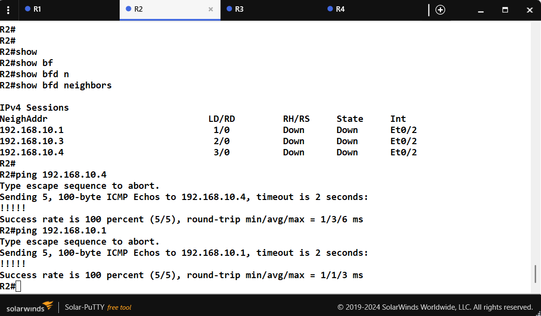
One of the prerequisites for a BFD session to be up and running is of course connectivity between the neighbors. As shown in your ping, this prerequisite has been fulfilled. However, there are additional reasons why the BFD session may be down. These include:
A BFD configuration mismatch - Ensure that BFD is configured on both ends of the link and verify that the bfd interval and bfd min-receive values match on both devices.
Ensure that the correct interface has been configured with BFD.
If you have tied BFD to a routing protocol such as OSPF as in the lesson, make sure that OSPF is operational, that it has been correctly configured to use BFD failure detection, and that it has successfully created an OSPF adjacency.
If you still have problems, you can use the following debug commands:
debug bfd events
debug bfd packets
debug ip bfd
Let us know how you get along and if we can be of further help!
What I got from this lesson was BFD is a really useful protocol to have in your network, and there is minimum that could go wrong with it. So, do you recommend this to use on every network with OSPF?
BFD is indeed an excellent protocol, and it is true that functionally, little can go wrong. But it should not be enabled everywhere with OSPF (or other routing protocols for that matter).
For many applications, OSPF alone is more than sufficient to fulfil the requirements of many situations. BFD should only be enabled on critical links where you need sub-second failure detection and where your platforms can support the associated resource overhead.
There are reasons why you should not enable BFD everywhere, and these include:
CPU/Resource Overhead: BFD sessions with millisecond timers create a continuous stream of control-plane packets. On modern hardware with hardware-assisted BFD, a few dozen sessions are negligible. However, on older platforms, software-based BFD, or with hundreds of sessions and very aggressive timers, CPU load can become significant and impact router stability.
Potential Instability: Overly aggressive timers on links that experience transient congestion, microbursts, or occasional packet loss can cause “false positives.” BFD may tear down OSPF adjacencies unnecessarily, causing route flapping and network instability rather than improving it.
Diminishing Returns: On directly connected physical links (fiber/copper), loss of signal already triggers immediate OSPF adjacency teardown. BFD adds little value here. Its real strength is on media where link failure doesn’t propagate physically such as Metro Ethernet, MPLS L2VPNs, GRE/IPsec tunnels, DWDM with holdover, or any Layer 2 transport that can “blackhole” traffic without dropping carrier.
So keeping these things in mind, BFD is a best practice for modern networks and should be part of your standard design. However, it should be applied intelligently, not universally. Deploy it where its benefits (sub-second detection) clearly outweigh its costs (CPU, potential instability), and always validate on your specific platform and workload before production deployment.