Thanks Brad, just fixed this typo.
Rene
Thanks Brad, just fixed this typo.
Rene
Hi Laz,
Why do we need two hardware tables? Why not just construct a single hardware table containing IP dest, Prefix, Next Hop IP and MAC? Surely this would be more efficient as aren’t two table lookups required using the FIB and Adjacency Table?
Is the need for two tables because the two hardware tables are stored in separate types of memory in the ASIC (CAM & TCAM)? ![]()
Thanks,
Gareth.
Hey Gareth
This is an interesting question Gareth, and I think you will agree with me that the answer is also very interesting. First of all, let’s take a look at the similarities and differences between CAM and TCAM.
What makes both of these memory types fast is the fact that all entries can be searched for in parallel. So if you have hundreds of entries, you can search for a particular value in all the entries in just a single clock cycle. The difference between the two has to do with the search algorithm that each uses, an algorithm that is hardwired into the circuitry of the memory itself.
CAM requires an exact match to return a result. This means that the value that is being searched for (in binary) must contain either 0s or 1s.
TCAM does not require an exact match, and is queried using 0s, 1s, and Xs, where X essentially means “anything” (that is, either 0 or 1). It’s kind of like a wildcard state. The name ternary CAM comes from the fact that you use three states rather than two.
Now applying this to networking devices, when looking up an address in the MAC table, you always require an exact match, so CAM is used. When looking up a prefix in a routing table, you don’t need an exact match, as long as the destination is contained within the prefix in the routing table, and that is where TCAM is used.
I hope this has been helpful!
Laz
Thanks Laz - by searching in parallel do yo mean searching in the CAM and TCAM at the same time?
This explanation helps a lot as to why two different tables are needed.
Hello Gareth
Actually, what I mean is that all entries of the CAM or TCAM table can be searched simultaneously. If you have a table with a list of 100 entries stored in regular memory, in order to search for a particular entry, say a specific MAC address, you will have to search sequentially in each row of the table. This would take 100 CPU cycles, assuming one cycle per entry.
CAM and TCAM memory allow all of the entries to be searched in parallel, simultaneously. That means that only one CPU cycle is needed to do the same lookup.
I hope this has been helpful!
Laz
Wow - the mind boggles at the speed in which hardware works at in our industry. Thanks Laz.
I come across a Cisco documentation. It’s about troubleshoot CEF routing loop.
https://www.cisco.com/c/en/us/support/docs/ip/express-forwarding-cef/26083-trouble-cef.html
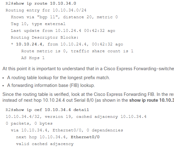
Since the FIB is based on RIB, how come in this article, the show ip route 10.10.34.0 result is different than the show ip cef 10.10.34.0 result?
Thanks,
Hello Helen
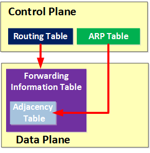
Remember that the FIB is created not only based on the RIB, but also on the ARP table. Remember this image?
In the example shown in the Cisco documentation, it is demonstrated that a specific sequence of events, with particular configuration parameters can result in an FIB that is incorrect and inconsistent with the RIB, for at least as long as the ARP entry exists in R2 for that particular host. In this particular case, if you look at the sequence of events at the end of the document that lead to this situation you can clearly see why there is a discrepancy in the RIB and FIB.
This is a little bit confusing and misleading. It is not saying that every time you forward a packet you check the routing table and then the FIB. That would be inefficient and would defeat the purpose of CEF. If the specific destination is not in the FIB, then we go to the routing table for routing, and the FIB is then populated appropriately.
We actually want to bypass the routing table to speed things up. So the example here is showing how the FIB can have conflicting information under particular circumstances. It is necessary to see both the RIB and the FIB during the troubleshooting procedures in order to pinpoint where the problem is. This is why we checked both the RIB and the FIB, saw the discrepancy, and the proceeded to see why the RIB was right and the FIB was wrong.
I hope this has been helpful!
Laz
Hi Laz,
Thank you for the explanation.
So as long as the ARP entry still exists in R2, it won’t update its fib table entry for this particular host even though the routing entry for this particular host has been already updated in its RIB, is this correct?
Hello Helen
Yes that is correct. But this is only the case because in this particular example, we have a floating static default route that uses only the egress interface without a next hop IP like so:
R2(config)#ip route 0.0.0.0 0.0.0.0 ethernet 0/0 10
Because there is no next hop IP in the route, an ARP request is sent out of that interface for the destination IP of the packet. Because proxy ARP is enabled on all routers, it receives the MAC address of R1 and sends the packet there. And because the FIB table uses the ARP table to populate it, it keeps the entry as long as the ARP entry exists…
In such a situation (and as a general best practice) it’s always a good idea to include the next hop IP in the floating static route.
I hope this has been helpful!
Laz
Thank you very much. It helps a lot!
Hi Laz ,
I am unable to understand cef and it’s purpose to use .
Kindly explain Tcam table ,process and fast switching in detail.
Its quite tough to understand this topic .
Rgds
Shivam Chaudhary
Hi
For recursive routing the next hop ip address is reachable or directly connected if we look up the touting table on R1 to reach Loopback of R3
Its look up 3 time in RIB ,which will create recursive behaviour .
Rgds
Shivam
Hello Shivam
When a router accepts a packet, it looks at the destination IP address to decide out of which interface it should be sent. This process of routing involves the destination address being loaded into memory, where the programming of the software will compare it with the routing table, which is also in memory, will process it using CPU power, and then decide out of which interface send it. All of this required the use of memory, CPU power, and software involvement. All of these components are in the Control Plane.
Higher end switches also contain dedicated hardware that contains various tables of information that will allow all of these routing processes to take place much faster. CEF takes advantage of this hardware so that routing can be performed at much higher speeds, allowing a device to provide even better performance. This specialized hardware is considered to be part of the Data Plane, and this is where CEF takes place.
We need CEF in order to be able to achieve the high throughput speeds that today’s devices can reach. How this works is described clearly within the lesson.
Take a look at this post to learn more about CAM and TCAM
Yes that is correct.
I hope this has been helpful!
Laz
Hi Laz ,
A) Would you please explain this term FIB table may or may not be held in TCAM Table . I can not decided the major difference between both Tcam and Fib table as both reside in data plan to forward ip packet
As go through with lesson you mentioned that Tcam table contain routing table , ACL and Qos detail and they do not choose the exact match of the ip packet to reach destination .
B)How to decide which one table is reside in which model of L2 , L3 switch and Router ?
C)Kindly confirm is data and control plane exit in Normal L2 switch
sir , why you mentioned about the CAM table while routing the ip packet as i know it only work for Layer 2 forwarding on the basis of destination Mac address when the traffic is transient but in routing the ip packet , we use interface of router as gateway . So how it fills it cam table during routing the ip packet
I am not relate the use of cam table as my understanding it is use for layer 2 forwarding when we talked about only transient traffic ,no use of interface mac address in L2Switch .
Please confirm how Layer 3 and router use Cam table as they use it interface mac address as a gateway How u relate cam during ip packet forwarding
Regards
Shivam Chaudhary
Hi Team ,
How L3 switch work when we have forward ethernet frame in terms of control plane and data plane and confirm is router use Cam table to forward ip packet .
Regards
ShivamChaudhary
Hello Shivam
I believe that your confusing comes from the use of the terms CAM and TCAM. CAM and TCAM are types of memory found in the hardware of the device:
They are not tables, but hardware memory that is used to store various pieces of information. This may be confusing because we often refer to the MAC address table as the CAM table, which is not correct.
So to clarify, the MAC address table, FIB, access lists, QoS information, and the routing table, are all data that are used to allow the operation of network devices.
CAM and TCAM are types of high-speed hardware memory that store these data.
Now as far as control and data plane go, where various types of data are stored depends upon the platform being used. High-end devices will have TCAM and CAM available in the data plane to include the FIB, and access-list information so that can be retrieved very quickly, and reduce data transmission delays that are introduced by going to conventional memory and software. Some lower-end devices won’t have that hardware available.
I hope this has been helpful!
Laz
Hi Rene / Laz Sir ,
I want to know from you i am not deciding why Cam is used in multi-layer switches or router .
Please share and detailed explaination of multilayer switches and router separately and kindly relate to cam and tcam table
Is router use cam table ?
Why L3 switches use cam table ?
How L3 switch work if they want to forward l2 frame in data plane ?
Sir i am not relate cam functionaliy in L3 switches or router .
Router not use layer 2 Forwarding but you use CAM Table in your article
See this post ![]()
in the example of a packet traveling from source to destination, if a packet’s destination is on a remote subnet, the packet’s destination MAC would be set to the gateway’s MAC. The switch would use the CAM to determine in which port the gateway resides, and it would send it there. Depending on the model hardware involved, the layer3 switch or router would use the FIB to decide what the next hop needs to be (and since the FIB might be in the TCAM–again depending on the model–the TCAM might be used in this process). This would continue until the packet arrives at the destination subnet, where the final switch would again use the CAM table to determine the destination’s MAC and corresponding port.
invest lot of days in this topic but not satisfied .
![]()
Hi team,
Kindly confirm below point :-
If we destined a packet which reside in different subnet .
How they learn the mac address or how they know which interface should be to sent a ethernet frame ?
Note- We have consider both devices layer 3 device or normal router
Laz sir please correct if I am wrong
If we talked about router they learner mac address through arp cache by doing this we can find the entering or existing interface for ethernet frame which contain ip packet in it .
If we talked about multilayer switch by default
We know that it can worked as layer 2 and layer 3 forwarding at wirespeed because they have ASCII hardware table where layer 2 and layer 3 information is placed ; Cam and Tcam .
Now my confusion how ethernet frame decide which interface of multilayer switch as a gateway should be used .How they know the outgoing port to which the frame should be sent .
I think they have using the information of cam table where source mac address information is stored ..
Rgds
Shivam
hi Authors,
I have learned that contorl plane protocols/static doesn’t install a route in the RIB if its egress interface is not resolved.
Why is it preferred to have a fully resolve route in RIB ?
What happens in the FIB when such a route is installed ?