CEF (Cisco Express Forwarding)

Hello Nguyen

It depends on the platform. For most platforms that support CEF, yes it is enabled by default, but it’s always a good idea to put in the command just to be sure.

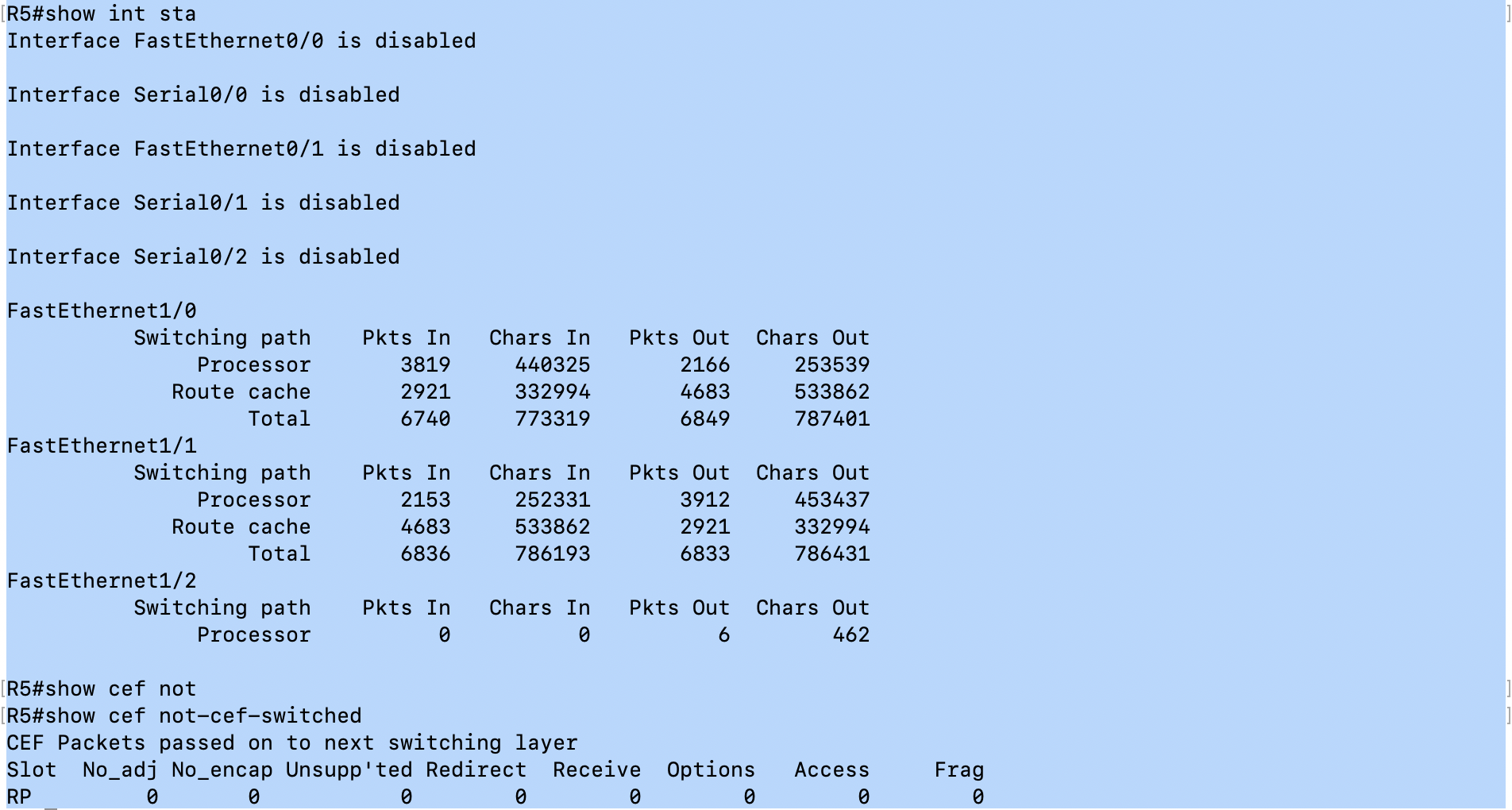
Yes, you will be able to configure either process switching or fast switching, once again, depending on the platform.

When configuring CEF, the only real option that affects functionality is the distributed keyword. Specifically, this enables distributed Cisco Express Forwarding operation to line cards. With this command, line cards perform express forwarding.

The other options are the following:

  • Accounting - this enables the collection of CEF based statistics to better understand CEF patterns
  • load-sharing - this option allows you to choose a load balancing algorithm when load sharing across multiple links
  • optimize neighbor resolution - this option is used to trigger Layer 2 address resolution of neighbors directly from CEF for IPv4
  • traffic-statistics - this option is used in conjucntion with NHRP

More information about these options can be found at the following Cisco Command Reference.

Finally, concerning the CEF memory, it depends on your GNS3 setup. Use the show ip cef command to see what prefixes are participating. Typical memory usage will depend on the platform and memory available, so on GNS3 it cannot be judged correctly.

I hope this has been helpful!

Laz

1 Like

After reading through the CEF lesson I need just a bit of clarification on the initial setup of the routes on R1 to reach the 3.3.3.3 loopback on R3.
Initially in your lesson you were setting up routes for connectivity between R1 / R2 / R3. On R1 you put a static route in for the R3 Loopback with the next hop as the R3 Fa0/0 interface 192.168.23.3–which is NOT directly connected to R1…
“ip route 3.3.3.3 255.255.255.0 192.168.23.3”, You also entered a route on R1 as "ip route 192.168.23.0 255.255.255.0 192.168.12.0. I do understand if our destination is network 192.168.23.0/24 we need this route. Its the next hop on the 3.3.3.0/24 this is confusing to me.
Why not just enter on R1 “ip route 3.3.3.0 255.255.255.0 192.168.12.2”
The packet would be forwarded to R2 (next hop directly connected) and R2 then has the route entered 3.3.3.3, (your static with next hop of R3 fa0/0 directly connected of R2. Why not just the route to the 3.3.3.3 with the next hop as R2 192.168.12.2? Was it necessary to show recursive just as an example?

1 Like

Thank Laz for your cool explain but the result that i show is on real devices , cisco ISR 4431. I confuse that what is threshold for CEF because when enter this command " show cef memory " , there many value , some of them increase to 99% :flushed:

Hello Matthew

Rene could have used the following setup:

ip route 3.3.3.0 255.255.255.0 192.168.12.2

and not care about what is needed to get to R3, since we could have R2 take care of that. However, for the purposes of the lab, and in order to show how CEF is beneficial, he created this routing scheme, which does indeed take three lookups to perform, and thus is relatively inefficient.

Because this example is exceptionally inefficient, it shows more clearly how CEF is important and improves efficiency.

I hope this has been helpful!

Laz

2 Likes

Hello Nguyen

I wouldn’t worry too much about the specific memory usage of each of these modules. The percentages are indeed close to 100% for many of them, but this is normal behavior. You can get more detailed in the actual meaning of these individual modules if you see that you are getting dropped packets or routing failures as part of your troubleshooting process.

I hope this has been helpful!

Laz

2 Likes

How router knows that packets belongs to same flow , and when another packet came it need to forward to control plane ??

Hello Muhammad

According to Cisco,

Fast switching allows higher throughput by switching a packet using a cache created by the initial packet sent to a particular destination. Destination addresses are stored in the high-speed cache to expedite forwarding.

You can find this at the following link:

So really, it’s not exactly a flow that is detected, but the same destination IP. Although packets may come from different sources, the destination is the same, and that is what is stored in the fast-switching cache.

So if a packet arrives at a Fast-Switching enabled router with a destination address of 10.10.10.10, this destination address is compared to the fast switching cache. If it’s in there, then the exit interface corresponding to that destination address is determined immediately (no lengthy recursive routing table lookups are necessary), and the packet is sent along its way.

I hope this has been helpful!

Laz

1 Like

Hello Laz,

In the attached screenshot, I am seeing ‘show int stat’ command shows that 3819 packets are processor switched on fasterethernet1/0 but ‘show cef not-cef-switched’ command does not show any processor switched packet numbers. Can you please explain why ? I am using GNS3.

Hello Sachin

This could be an issue concerning the deprecated command. Since 12.2(25)S, this command has been removed. A more useful command is the show ip cef switching statistics command about which you can find out at this Cisco command reference.

Try this command out and let us know your results.

I hope this has been helpful!

Laz

1 Like

Hi Rene,

Valid cached adjacency on which type of adjacency resides?

What kind of issues can troubleshoot with cef?

Thank you

Hello Juan

There are six types of adjacencies. One type is valid cached adjacency. The others are described in the lesson as well. Each one is distinct and is not related. So there is Null, Drop, Discard, Punt, Glean, and Valid.

Concerning troubleshooting, there are various methods that you can use. Specifically for troubleshooting incomplete adjacencies with CEF, you can take a look at this Cisco documentation:

I hope this has been helpful!

Laz

1 Like

Hello Laz,

I am trying to understand ‘Discard adjacency’.

I am using 3 routers R1,R2 and R3. ospf is running between all the three routers and all the interfaces of R3 can be pinged from R1. But if I apply an ACL on R2’s interface so that R1 can not ping R3 then I do not see ‘discard adjacency’ in R2’s CEF table.

According to following definition I should be seeing discard state.
‘discard adjacency: this is for packets that have to be discarded because of an access-list or other policy.’

Thanks,
Sachin

Hello Sachin,
CEF discard adjacencies are used for addresses that are part of a loopback interface´s subnet, but are not actually configured on the loopback interface.

For example if you configure loopback interface ip as 1.1.1.1/24, this is going to produce discard adjacency for all IPs from 1.1.1.2 to 1.1.1.254.
All packets received by router and desitined to these IP addresses are going to be silently dropped, because packets dropped by discard adjacency do not generate ICMP messages by default.

Look at this example:

R1(config)# interface loopback 0
R1(config-if)# ip address 1.1.1.1 255.255.255.0

R1(config)# interface loopback 1
R1(config-if)# ip address 11.11.11.11 255.255.255.255

Now lets list all CEF discard adjacencies:

R1# show ip cef adjacency discard
Prefix               Next Hop             Interface
1.1.1.0/24           attached             Loopback0

Only loopback0 is showing as discard, it is because we configured it as /24.

You can look at it in more detail.

CEF adjacency for 1.1.1.1 (configured as IP on /24 loopback):

R1# show ip cef 1.1.1.1 internal
1.1.1.1/32, epoch 0, flags [rcv, local, SrcElgbl], intf-rcv, RIB[C], refcnt 5, per-destination sharing
  sources: I/F, RIB 
  feature space:
    IPRM: 0x0003C00C
  subblocks:
    gsb Connected receive chain(0): 0x13CC9F00
    Interface source: Loopback0 flags: local, source eligible
  ifnums: (none)
  path list 13CC9E3C, 5 locks, per-destination, flags 0x41 [shble, hwcn]
    path 124C79CC, share 1/1, type receive, for IPv4
      receive for Loopback0
  output chain:
    receive

CEF adjacency for 1.1.1.2 (same subnet as loopback, but not configured on loopback):

R1# show ip cef 1.1.1.2 internal
1.1.1.0/24, epoch 0, flags [att, cnn, cover, deagg], RIB[C], refcnt 5, per-destination sharing
  sources: RIB 
  feature space:
    IPRM: 0x0003800C
  subblocks:
    gsb Connected chain head(1): 0x1170F828
    Covered dependent prefixes: 2
      need deagg: 2
  ifnums:
    Loopback0(13)
  path list 12BC052C, 3 locks, per-destination, flags 0x49 [shble, rif, hwcn]
    path 12BC0764, share 1/1, type connected prefix, for IPv4
      connected to Loopback0, discard
  output chain:
    discard

CEF adjacency for 11.11.11.11 (configured as /32 on loopback):

R1# show ip cef 11.11.11.11 internal
11.11.11.11/32, epoch 0, flags [att, cnn, rcv, local, SrcElgbl], intf-rcv, RIB[C], refcnt 5, per-destination sharing
  sources: I/F, RIB 
  feature space:
    IPRM: 0x0003800C
  subblocks:
    gsb Connected receive chain(0): 0x13F58ED0
    gsb Connected chain head(1): 0x13F58BC8
    Interface source: Loopback1 flags: local, source eligible
  ifnums: (none)
  path list 13CC9CAC, 3 locks, per-destination, flags 0x41 [shble, hwcn]
    path 124C77B0, share 1/1, type receive, for IPv4
      receive for Loopback1
  output chain:
    receive
2 Likes

Hi Rene,
I confuse about how is the relation of CAM, TCAM and FIB , adjacency table in CEF.

Hello Nyi Nyi

Take a look at this post.

If you have any additional questions or you need additional clarification, let us know!

Laz

2 Likes

"In the example above I have three routers. R3 has a loopback interface that we want to reach from R1. I will use static routes for reachability:

R1(config)#ip route 3.3.3.0 255.255.255.0 192.168.23.3
R1(config)#ip route 192.168.23.0 255.255.255.0 192.168.12.2

The first static route is to reach the loopback0 interface of R3 and points to the FastEthernet0/0 interface of R3. The second static route is required to reach network 192.168.23.0/24."

I don’t understand why you would configure 192.168.23.3 as your next hop interface in order to get to that network. I would think that 192.168.12.1 or .2 as a next hop would be sufficient to get that route to route effectively. you aren’t going to necessarily know in the case of a external resource what the IP address is of the interface that 192.168.23.3 is currently inhabiting in the case of having a provider.

ip route { ip-prefix | ip-addr/ip-mask } {[ next-hop | nh-prefix ] | [ interface next-hop | nh-prefix ]} [ name nexthop-name] [ tag tag-value] [ pref ]

Hello Adam

The purpose of this example is to demonstrate in what kinds of situations CEF comes in handy. The specific configuration is valid because you can indeed route a particular destination via a next hop IP that is not directly connected as long as you have another route that will tell you how to get to that next hop. This is called a recursive lookup in the routing table, or recursive routing.

You are correct, that simply putting in the ip route 3.3.3.0 255.255.255.0 192.168.12.2 entry would be sufficient, and would actually be more correct, however, Rene is deliberately creating an inefficient routing scenario to demonstrate how CEF can make it efficient.

I hope this has been helpful!

Laz

3 Likes

Just below the diagram showing the processing of an IP packet arriving at a multilayer switch and how it is processed is the sentence that states “The multilayer switch will check the routing table, notices that 192.168.20 /24 is directly connected…”. You will notice that the IP address in that sentence has only 3 octets!
Brad

Hello Brad

Thanks for the heads up, I will let Rene know to have that fixed.

Thanks again!

Laz

Just below the diagram showing the processing of an IP packet arriving at a multilayer switch and how it is processed is the sentence that states “The multilayer switch will check the routing table, notices that 192.168.20 /24 is directly connected…”. You will notice that the IP address in that sentence has only 3 octets!
Brad

1 Like