Hi Rene,
I’m trying to design a campus LAN network where L3 functions will be moved to a DC Firewall (Fortigate). However, I’m confused about how to design this with Cisco Core 6800(collapsed core-vss) with Fortigate as DC firewall in A-P. What would be the right way to cable this scenario?
Hello Midhul
Based on your description, your collapsed core approach would look something like this::
                 [Fortigate FW]          -Core/Distribution
                    /     \
                [6800 VSS pair]          -Access
               /    /      \   \
          [host] [host] [host] [host]
Let me make some assumptions. You mention “A-P” which I assume you mean Active/Passive mode or some form of high availability, right? I’m assuming the Fortigate firewall will consist of at least two entities (appliances or virtual) that will operate in active/passive mode. Also moving L3 to the FWs means that you are making your pair of 6800s function only as layer 2 devices.
Remember, the pair of 6800s using VSS operate virtually as a single switch.
With these assumptions, let me suggest the following guidelines:
- Make one physical connection between each FW and each 6800 chassis. This will ensure redundancy across the physical hardware of the 6800s as well as the links to both physical devices.
- The connections from each FW to each physical 6800 should be configured as trunk links. On the FW side, you should configure “router on a stick”.
- Make sure that all of the VLANs in your network are included and represented in the configuration of the subinterfaces of the FW and of the trunk configuration on the 6800 side.
Now how to achieve the required high availability from the Active/Passive configuration you will make on the Fortigate FWs will depend upon the configuration and the setup of those devices.
Just a comment here, what is the reason you want the FW to perform routing? This setup essentially uses the 6800s as access switches, which is kind of a shame because of their capabilities and robustness. I would consider routing by the 6800 VSSes to be much more robust and reliable. If there is a way to keep routing at the 6800s, I would go for it. Just a thought.
I hope this has been helpful!
Laz
Hello, I’m looking the way I can design a high level Network architecture, what component should I add to achieve Availability, if anyone has any kindly share with me.
Hello @nyadeos ,
That is a broad question. There are many things that influence high availability.
Here are some things to consider:
-
Redundant hardware: having more than one router/switch/firewall where appropriate. Some devices have redundant power supplies and supervisors.
-
Failover/protocols: There are many protocols that help with failover and redundancy. To give you two examples for routing: HSRP or VRRP.
-
Backup power: UPS, etc.
-
Network monitoring
-
Disaster recovery plan
These are some high-level things to think about. It depends on your network and how critical it is.
Rene
@ReneMolenaar yes it is broad question but specifically I was having assignment to design a network architecture with high availability is in that regard I was looking one of them
Hello Deo
As Rene suggested, high availability can be deployed with multiple technologies depending upon what you want to achieve. Here are some thoughts that might help you out:
- High availability can be achieved using two or more devices to perform a task.
- Setting up two ASAs for example in high availability mode, or two servers mirroring each other.
- Configuring switches in various high availability arrangements like StackWIse, vPC, and VSS.
- Applying First Hop Redundancy Protocols (FHRPs) like HSRP, VRRP, and GLBP to enable multiple devices to act as default gateways.
- High availability can also be achieved using technologies that use multiple physical links like EtherChannel.
- Routing can be configured to introduce Equal Cost MultiPath (ECMP) Routing delivering high availability and resistance to the network.
- High availability can also be achieved by implementing the appropriate power supplies, making sure that you have redundant power supplies per device, and UPS systems delivering power to your network devices.
- High availability can also be delivered by designing your network with duplicate data centers, where if one data center fails, the other will take over fully. This is a higher-level design aspect, and assumes that your organization has multiple sites.
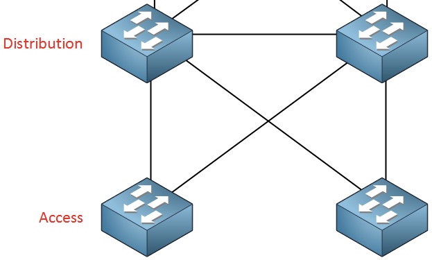
- Network design delivers high availability by using either a spine and leaf architecture, which is inherently redundant, or a 3 tier campus network design as shown in this lesson.
These are just some of the areas in which high availability can be implemented into network design. If you would like us to expand on any particular area, let us know…
I hope this has been helpful!
Laz
Hi everyone! I have a question regarding the topology used in the lesson.
As far as I am aware of, Cisco‘s recommendation is as follows:
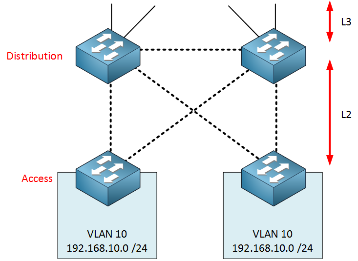
- One VLAN spanning both access switches = Use L2 between the distribution switches. STP would avoid a loop, FHRP communication can be sent/received on the L2 link between the distribution switches.
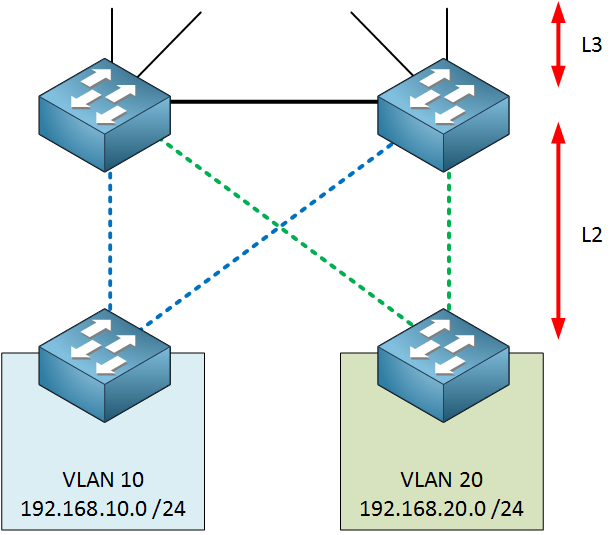
- One VLAN confining to each access switch = Use L3 between both distribution switches. No STP needed, FHRP communication would go through the access switches.
Is there a reason for why not also using a L3 link between the distribution switches in scenario 1)?
Hello Marcel
Yes this is correct.
Yes there is. If you want to span a single VLAN across two access switches, then you must achieve Layer 2 connectivity between those switches.
Remember, you would typically have one IP subnet assigned to each VLAN. So if you have VLAN 10 on both access switches, and you have two hosts, one on each access switch with IP addresses 192.168.10.10/24 and 192.168.10.11/24, then these hosts must communicate with each other on Layer 2. In other words, those two devices must be on the same broadcast domain. If you have configured Layer 3 connectivity between the access switches and the distribution switch, then you are splitting up that broadcast domain, and you are requiring routing to take place between them. But they’re on the same subnet! So you see, from a design standpoint, this won’t work.
The VLAN assignments, IP address subnets, and the access and distribution network design must line up so that layer 2 connectivity is available between all devices that exist on the same subnet/VLAN/network segment. Does that make sense?
I hope this has been helpful!
Laz
Hi Rene/Laz,
I went through some of your explanations for why the link between the distribution switches must be Layer-2. However can you confirm the following?
- The distribution switches on either side will have lower bridge priorities or they act as primary/secondary root switches as traffic will always flow through them as they aggregate the access-layer traffic?
- The use of routers on the access layers is not a viable option if cost is an issue? That’s the reason to use layer-2 switches in access layer?
- Also, can you explain why having 2 different VLAN’s on access-layer switches on the left and right hand side would be beneficial?
Thnaks,
Adi
Hello Adhithya
The distribution switches should typically have lower bridge priorities and act as primary/secondary root switches. This is done to ensure that they are chosen as the root bridge in the spanning tree protocol, which in turn ensures that traffic will always flow through them as they aggregate the access-layer traffic.
It’s not just an issue of cost, but of the function of the device as well. At the access layer, you typically have many devices on the same subnet. Routers are devices that have a different subnet connected to each port, so using a router at the access layer would be impractical. Now maybe you meant using a Layer 3 switch at the access layer? If so then yes, the issue is primarily cost. You wouldn’t employ routing at the access layer very often, so using a Layer 3 switch there would simply mean you have a capability that you will rarely or never use, unless your network design specifically requires it.
If you segregate your VLANs such that VLAN 10 exists only on the left switch and VLAN 20 on the right switch, that will allow you to enable a Layer 3 link between your distribution switches, and it would eliminate the use of STP. Thus, you would never have a blocked port, so the available bandwidth of all links is being used! Does that make sense?
I hope this has been helpful!
Laz
@lagapidis Yes I understand the concept now. You also mentioned the distribution switches have a virtual gateway IP address. Why is that? Is it used as a gateway for hosts connected to access switches? Why do we need a virtual ip on a physical L3 distribution switch ?
Hello Adhithya
I believe you are referring to this statement from the lesson:
The switches on the distribution layer will use a protocol to create a virtual gateway IP address. We need layer two connectivity for this and you don’t want this traffic to go through the access layer.
In the lesson, Rene makes this statement as a reason for maintaining a Layer 2 connection between distribution switches. When Rene refers to a virtual IP address, he is referring to the use of a First Hop Redundancy Protocol (FHRP) such as HSRP, VRRP, or GLBP. These protocols use virtual IP addresses to allow gateway redundancy.
Now why is Rene saying that it’s preferable to maintain an L2 connection between such devices? The answer is in this NetworkLessons note on the topic. This note talks specifically about HSRP, but it is valid for all FHRP protocols.
I hope this has been helpful!
Laz
Great Article. One question. In the “Loop Free” design where VLANs are not spanned across multiple Access Switches, is there where GLBP is most appropriate where HSRP/VRRP are best suited for the “Looped” topology?
Thank you.
Hello Chris
The Loop-free design you are referring to simply eliminates the need for STP to block a port to avoid a Layer 2 loop. Since no layer 2 loops can be formed, STP does not need to block any ports.
This doesn’t have a direct bearing on the choice of FHRP protocol (GLBP, HSRP, or VRRP). You can use any one you like and the results will be similar. You can use any one for either the “loop free” or the “looped” topology. Can you share with us what you had in mind and why you consider GLBP more appropriate for the loop free topology? Let us know so that we can help you further!
I hope this has been helpful!
Laz
Lazarus,
Thank you. I was thinking since both uplinks from the Access switch to the Dist Switch are forwarding in the Loop Free model, GLBP might be a more appropriate design choice because it would allow for both uplinks to be used simultaneously to send traffic outside the subnet since both dist switches could forward for the vlan. With HSRP/VRRP, only one of the uplinks could be used at any one time since there is only 1 active forwarder for the VLAN.
Thank you.
Hello Chris
Ah, I see, thanks for the clarification. My initial explanation still stands, however, I will further clarify the issue here.
STP is a purely Layer 2 feature and its purpose is to ensure that the topology does not create a Layer 2 loop which may result in undesirable behavior as you probably already know.
GLBP, HSRP, and VRRP are Layer 3 features that allow redundancy for the first hop (i.e. the default gateway). That’s why they are referred to as first hop redundancy protocols (FHRPs).
Now when any FHRP protocol uses two or more devices as redundant default gateways, at Layer 3 it simply desires connectivity to the IP address of each device in question. It doesn’t care, nor does it deal with the actual Layer 2 path that will be taken to reach those redundant gateways.
So even if you were to be able to have two or more Layer 2 paths to the two or more redundant default gateways, the actual path or link that will be followed to achieve the redundancy is not affected at all by GLBP. Once the packet is encapsulated and is given a destination MAC address, only Layer 2 operations dictate the path it will take to the actual default gateway device. Does that make sense?
Now having said that, where high performance and network efficiency is needed, such as in datacenters, it is always beneficial to use Layer 2 technologies that do not block ports, such as TRILL, VXLAN, vPC, EtherChannel, etc. These should be employed in such scenarios but will not ultimately affect the choice of FHRP protocol to use at Layer 3.
I hope this has been helpful!
Laz
Hello, everyone. I don’t understand something here.
Because VLAN 10 is used on both access layer switches, the link between the two distribution layer switches HAS to be a layer 2 link as well. There are two reasons for this:
If one of the uplinks from the access to the distribution layer fails, VLAN 10 traffic could go through the access layer.
The switches on the distribution layer will use a protocol to create a virtual gateway IP address. We need layer two connectivity for this and you don’t want this traffic to go through the access layer.
In this topology, won’t the DSW switches still run a FHRP protocol for both VLANs? This means that the HSRP messages will go through the access layer since the link between them is L3, or not?
David.
Hello David
Yes, the distribution switches can be configured to run an FHRP for redundancy. The FHRP messages must travel between the switches on a Layer 2 segment. In this case, they would travel through the access layer switches. However, for FHRP, best practice would dictate that there should be an L2 link between the switches for this purpose.
I hope this has been helpful!
Laz