Cisco Campus Network Design Basics

Hello José

Wow, that’s a lot of questions! I will do my best to address them.

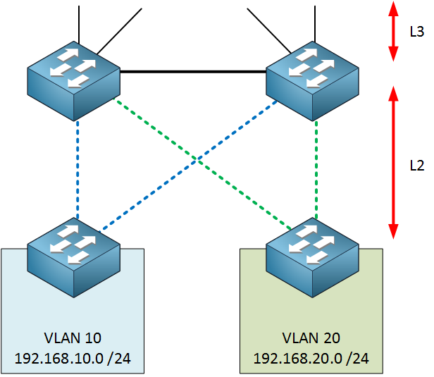
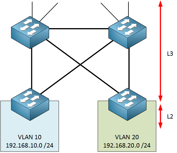
If the VLAN exists on two different switch blocks then yes, you must ensure that you have Layer 2 connectivity across the core devices. However, it is best practice to try to keep VLANs contained within each switch block so that the core performs only routing.

It depends on your design. Best practice dictates that the core should perform routing between switch blocks. If the core devices are L3 switches, which they typically are, then you would create SVIs with IP addresses to act as the next hop IPs or default gateways. If they’re routers, then each interface would have its own IP address to act as the gateway/next hop. Some routing would also take place at the distribution layer to avoid having intra-block traffic go to the core and come back.

If that were the case, traffic between subnets would be routed at the access layer. Such traffic would not reach the distribution or core layers at all.

Yes

Typically you would add another switchblock and call it “network edge” where the edge equipment would be (edge router, firewall, IDS, IPS etc) to connect to the “outside world” either to the Internet or via MPLS to remote sites.

See answer above.

Yes that can happen, but it is best practice not to span VLANs across campuses. VLANs should not be spanned across switch blocks if at all possible. You should have only routing across any tunnels you create or across MPLS.

Layer 3 switches are preferable because you can create as many SVIs as you like to serve each individual subnet in your topology, where using a router, you are limited by the physical interfaces that exist on the device.

This design is for any enterprise network that is generally large. Whether it is in one large building or in several buildings on a campus makes no difference. For branch office networks, it all depends upon the size. If they’re large enough they too should conform to these campus network design principles.

VSS will indeed negate the need for FHRP and STP however, it has limitations. VSS can only connect two core devices and is supported only on the older catalyst 6500 and 4500 series switches. A better alternative is to use either Stackwise Virtual or a more traditional FHRP arrangement. Still other options include the use of a spine and leaf architecture, but those are more often used in data centers, although not exclusively so.

I hope this has been helpful!

Laz

why don’t interconnect access layer switch ?

Hello Chinmay

Hmm, that’s a good question! There are actually several reasons for this:

First of all, each access layer switch is typically located at a different physical location. For every telecom closet that serves, say a particular floor of a building, you would typically have one access switch. If you were to interconnect access switches in different locations, you would need structured cabling that terminates between such telecom closets on each floor. This is not generally done because the logic behind structured cabling is that it is a “tree” structure, where the access layer switches are the leaves and there are no connections between leaves.

Secondly, if you happen to have more switches at each telecom closet to server a larger number of devices, you would typically connect those together not via Ethernet, but via other technologies such as StackWise, VSS, or vPC to name a few. This makes those multiple switches function logically as a single switch, allowing you to maintain the single switch per access layer location.

Thirdly, when you configure VLANs, you want to confine each VLAN as much as possible to as few access switches as possible. You don’t want to span VLANs across multiple access layer switches that may exist on different floors or even in different buildings. This design principle means that communication between hosts on multiple access layer switches should take place via routing, which is something that exists not in the access layer, but in the distribution layer and the core layer. So there is no need for physical connections between access layer switches.

I hope this has been helpful!

Laz

I am currently going through the network architecture section of the latest ENCOR book. Where it talks about having either a layer 2 or layer 3 connection between a distribution switch pair. For some reason, it’s not clicking with me.

For a layer 2 access layer:

If you have a vlan spanning multiple access switches, then you want to use a layer 2 interconnect and if you have a vlan confined to a single access switch, then you want to user a layer 3 interconnect.

Why? I someone could explain this in the simplest terms, it would greatly be appreciated.

Hello Terry

Best practice for network design is to try to confine your VLANs to as small an area as possible. That is, if you can confine a VLAN to a single access switch or at least to a set of access switches in the same rack/telecom closet, that would be ideal. Why? Well, take a look at this diagram. Although they’re not labeled, we can clearly see the core, distribution and access layers.

Now imagine that the two PCs are on the same VLAN. If this is the case, then the distribution switch that connects the two access switches should have Layer 2 connectivity with those switches. i.e. the connections between the three switches are trunks and should include the PCs’ VLAN ID as allowed on both trunks. In this way, one PC should be able to communicate with the other without the need for any routing.

However, if the two PCs are on different VLANs, the intervening distribution switch should be a Layer 3 switch and should perform routing. Each of the VLANs would have its corresponding SVI in the distribution switch, which can perform inter-VLAN routing to achieve communication.

Ideally, the latter situation should be implemented because you are confining VLANs (and thus broadcast domains) to smaller portions of the network, making the network more efficient. Does that make sense?

I hope this has been helpful!

Laz

Which is the difference between Backplane and SwitchFabric ?

Hello Juan

The two terms are related of course. The backplane is more of a hardware term. It is the physical circuit board that interconnects the ports on the switch. If you were to open up a switch, it would be the circuit board to which all of the ports are connected. It’s also where other physical components like the power supply, memory, and any processors are connected to. It’s kind of like the motherboard of the switch, but refers mostly to the physical path or backbone through which data packets travel from one port to another. The capacity of the backplane (measured in bps - bits per second) determines the maximum data throughput of the switch.

Switch Fabric, on the other hand, is the mechanism that controls how data travels across the backplane. It’s like the traffic management system of the switch. The switch fabric makes decisions on how to route the packets of data to their correct destination ports. It’s responsible for ensuring efficient and reliable data transmission within the switch. It includes the “intelligence” or the logical capabilities of a switch, which runs on top of the backplane. Does that make sense?

I hope this has been helpful!

Laz

Thank you for your reply @lagapidis

Yes, i’ve also made the same analogy with a PC Motherboard.

So, the Switch Fabric always exist ? even in lower end networking devices (by lower end i mean Enterprise devices such as Cisco ISR). For example, in SP enviroment we could find Cisco ASR9K nodes and in the documentation about its architecture i’ve never seen the term backplane but switch fabric, np (network processor), and so on… the obvious answer is due to this particular architecture.

I’ve also read another difference is, backplane like a motheboard has a bus architecture, and the switchfabric is a matrix.

But relying on your explanation, i think i get the main differences. In a nutshell, backplane is the physical board where linecards are inserted (Many Enterprise devices does not support this because most of them have integrated ports), andtherefore a particular backplane has a max BW or pps that can process. In the other hand the SwitchFabric is the “brain” that decides how packets must travel across the backplane.

i have a a couple of questions : In those network devices that you have a backplane and integrated ports, if the backplane fails could be replaced with a new backplane ? (such as a failed motherboard), the Switch Fabric is not a physical card, is it a process running on the backplane ?

Hello Juan

Yes, both backplane and switching fabric exist in all networking devices, including even the lowest-end devices. The switching fabric is essentially the integrated set of hardware and software resources within a switch or router that provides the logic, mechanisms, and architecture to switch data between ports. Even a 10-dollar unmanaged 5-port switch will have some level of software and logic circuits that comprises a switching fabric.

Also keep in mind that the backplane is kind of like the “motherboard” but it doesn’t necessarily need to be detachable like that of a computer. It may just be the circuit board onto which the port circuitry is hardwired. In any case, it is comprised of the hardware circuitry, whether detachable or not.

If the backplane fails, it really depends on the switch if you can replace it or not. For lower end devices, these are typically hardwired, so if it fails, the whole device requires replacement. Even for higher end devices, backplane is an integral part of the chassis so it’s not a trivial thing to simply pull it out and replace it. For modular switches, such as the Nexus 7000 or the Catalyst 9400, you can pull out and replace line cards. However, the backplane which is designed to be part of the chassis is not designed to be replaceable by the customer. If there is any failure, any replacement would have to be performed by specialized technicians.

The switching fabric is not a physical component but has a large logical (software) component so it is not replaceable in the same sense.

I hope this has been helpful!

Laz

1 Like

Hello Guys
I want to make a backbone change in a network with critical network infrastructure, I want to minimize downtime.
the old backbone is procurve
the new Backbone is Aruba CX

There are 12 switches and 10 routers connected to this backbone

There are no dynamic routes in the backbone, everything is done with static routes
hundreds of ACLs.

Do I need to clear the arp table one by one on all switches and routers connected to this backbone?
Do I need to statically enter the ARP table?
or what should I do to minimize the interruption?

I would appreciate if you give detailed information.

Hello Dennis

Making such changes to the backbone of critical network infrastructure can be difficult. All precautions must be taken to ensure that downtime is minimized.

I would not be too concerned about the ARP tables involved. The delay that they will introduce is minimal compared to some other concerns you should have in mind. First of all, if the switches are layer 2 switches, they don’t maintain an ARP table since they serve transient layer 2 traffic. Since the switches themselves are not the source or destination of this traffic, no ARP tables are necessary. For Layer 3 devices such as the routers, or any Layer 3 switches, the ARP tables they maintain are minimal in size, since they typically need ARP to resolve the next hop address, or, if they serve as a default gateway for a subnet of users, it is used to reach the final destination. But again, as soon as the network is up and running again, the ARP tables will be repopulated within a matter of seconds.

I would be more concerned with issues such as:

  • Ensuring the appropriate migration strategy - Will you use a phased approach? Will you temporarily run both the old and new backbones together in parallel?
  • Have you created a lab simulation - Creating a lab simulation of the setup can be helpful to catch any errors in the configs of the new devices.
  • How are you transferring old configs to new? Are you using Aruba CX? How are you transferring the static routing and the ACL configuration from the old devices to the new ones? Should these be tested either on the live devices before they’re installed, or in a simulation?
  • Fallback plan - Make sure that you have a plan to reinstate the old backbone in the event that there is an unsolvable problem with the new infrastructure, so that you can quickly revert in the event of unforeseen problems.
  • Post migration - After you’re done, what tests should you run to ensure everything is working correctly?

These are just some of the things you will have to think about when migrating, and many of these issues can be much more disruptive than the repopulation of an ARP table. If you have any more specific questions bout these or other processes in the migration procedure, please let us know!

I hope this has been helpful!

Laz

Hi Team,

How to resolve high memory usage issues in switches?

Regards
Srikar

Hello Sonti

High CPU usage on a Cisco switch can be caused by several factors including:

  1. Large MAC address table - The MAC address table takes up memory, and if it gets too large, it can use excessive amounts of memory. This will typically indicate a MAC flooding attack where a large number of spoofed MAC addresses are sent to the switch causing the MAC address table to overflow. Use the show mac address-table command to
  2. Excessive logging - Check to see if you have any ACL logging or debugs set up, and check what the size of the local logging buffer is. If it is too large, you may be overflowing the memory.
  3. Malware or DDoS attacks - These may also cause high memory usage. In this case you should use network security tools to identify and block malicious traffic. One quick and dirty solution is to implement ACLs that will allow only acceptable traffic.
  4. Routing tables - If your switch is a Layer 3 switch, a very large routing table will also cause high memory usage.
  5. Large ARP tables - ARP tables are another construct that switches use, and if these get too large, this is another source of high memory usage. Unusually large ARP tables may be a result of APR spoofing attacks and should be investigated.

These are just some of the causes of high memory usage and are by no means exhaustive. However, to resolve such issues, you must monitor the memory usage on the switch. This can be done by using certain CLI commands that show the status of the memory and how it is being utilized.

  • Check Memory Statistics:
    • Use the show memory command to display detailed statistics about memory usage.
    • Use the show processes memory command to display memory usage for each process
    • Use the show processes memory sorted command to display the memory usage of all processes, sorted by the amount of memory used.running on the switch.
  • Check Buffer Statistics:
    • Use the show buffers command to display buffer statistics. Buffers are used by the switch to temporarily store data packets.
  • Check I/O Memory:
    • Use the show memory io command to display the I/O memory statistics.

These are just some of the commands that can get you started in troubleshooting high memory usage on a Cisco switch.

I hope this has been helpful!

Laz

I have the responsibility of configuring about 50 new switches per site (11 sites) to replace old ones. how best can I automate this. I don’t want to manually copy the config and paste on the new switch.

I need help.

Hello Temitope

Wow, that’s a colossal task, but an interesting one, and one that you will learn a lot from! There are several tools and methodologies you can use, however, I’d like to ask some clarification questions.

  1. At each site, you already have a network up and running and you need to replace the current switches with new ones while keeping the same topology, at least initially? Is that right?
  2. Are the old and new switches Cisco or are you using different vendors?
  3. Do you currently have remote access to all of the existing switches at these sites?

Based on the above questions, I can help you to formulate a high level plan to help automate some of your tasks. In general, scripting, configuration management tools, network automation tools, and template mechanisms available on some switches allow you to speed up the process, but a lot of what you can do depends upon the current status of your networks. Let me know the above so I can help you further in your task…

I hope this has been helpful!

Laz

How can I make a clos topology in non-blocking supporting at least 100 hosts. I can only use a switch with max 8 ports.
Need help in understanding this,can someone help?

Hello Kiran

The restriction of using switches with a maximum of 8 ports is very impractical and costly, so I’m assuming that this is a question from an exercise for a university course on networking. In any case, let’s first take a look at what a “Clos network” is.

A “Clos network” refers to a multistage, non-blocking switch architecture designed by Charles Clos in the 1950s for telephone exchanges. Since its original inception, the principles behind the Clos network have been applied to data center architectures, especially for scalable and efficient network switches. A modern spine and leaf topology is actually a type of collapsed Clos network.

Take a look at this to find out more about it.

Strictly speaking, a Clos network must be non-blocking and typically has three stages: the ingress, the middle, and the egress. Each ingress switch must be connected to all middle switches. However, this is not possible with 8 port switches, so we’ll have to do two things: Increase the number of stages and separate the ingress tier into pods.

To be able to get a definitive solution we would need to know more about the restrictions that the Clos network has. Are we looking at a datacenter spine and leaf type topology with two, three, or even four tiers, or are we looking at a classical Clos network with both ingress and egress switches? If you give us some more information, we can dig deeper to get to a solution.

I hope this has been helpful!

Laz

Hello Rene!
Thanks for the lesson, i appreciate details mentionned on it. I have one note about STP protocol i didn’t see the mention of it, over ther part between Core & Distribution Switches.

Hello Youssef

The use of spanning tree protocol (STP) does play a vital role in the three-tier network design model. It plays a role in the particular model layer that is configured to use Layer 2.

In the three-tier model, typically, communication between the core and distribution layers functions at Layer 3, where routing is configured. It would be rare to see an L2 setup between the core and distribution layers, as such an approach would not be scalable. So you almost never see STP operate between the core and distribution layers.

As stated in the lesson, you could have Layer 2 functioning between the distribution and access layers where STP would be employed, such as in the following diagram:

or you could move the operation of Layer 3 all the way down to the access layer switches like so:

In such a case, STP would not play a role. Does that make sense?

I hope this has been helpful!

Laz

1 Like

Ohhhh! such a good explanation, now i can relate with the use of the L2 just between Distribution and Access layer.

Thank you ! i appreciate the details :blush:

1 Like