By default, SPAN and RSPAN sessions will only send untagged packets to the destination port. In addition, control traffic such as CDP, VTP, DTP, STP, PAgP, LACP and others are not captured by default. However, you can use the encapsulation replicate keywords when configuring a destination port, and the following will take place:
Packets are sent to the destination port with the same encapsulation as they arrive on the monitored port, whether tagged or untagged.
Packets of all types, including those of the protocols mentioned above, for both layer 2 and layer 3 are also captured and sent to the destination port.
Now note that this is only the case for local SPAN. RSPAN does not support the encapsulation replicate functionality, so if you want to capture STP packets and BPDUs, then you must use SPAN.
Just a note, you mention STP events, but I assume you mean BPDUs. If you want to see STP events then you can use the appropriate debug commands on the CLI of the switch in question. Take a look at the following Cisco documentation for more info:
In order to help in the troublshooting process, please share with us your SPAN configuration as well. Please let us know the platform you are running on, the IOS version, and also, describe to us the kind of test traffic that you created in order to capture data using SPAN.
Now having said that, I can tell you what I believe may be happening. It looks like all three VLANs are configured to capture both incoming and outgoing traffic. However, some platforms, such as certain Nexus devices, are capable of only supporting incoming traffic on VLANs when they are specified to participate in SPAN, even though they have been configured for both incoming and outgoing. Could it be that yours is such a case and your traffic is incoming on one VLAN and outgoing on the other two, so you are only getting traffic from one VLAN? Try both sending and receiving traffic on all VLANs to verify.
If this is not the case, then we’ll have to take a look at the details you send us to further help you in the troubleshooting process.
i have two nexus switches and created a span port on each device. I am seeing traffic on one switch and not on another even though it has the same configuration..
Nexus is not allowing two destination ports to connect in same switch.in the monitor session
In the above scenario i have getting traffic only one way RTP traffic and not the other.
and i tried with cisco IOS with two destination ports as below
monitor session 2 destination interface Gi2/19 - 20
GigabitEthernet2/19 is up, line protocol is down (monitoring)
GigabitEthernet2/20 is up, line protocol is down (monitoring)
When it comes to SPAN on a Nexus device, keep the following in mind:
When you specify a VLAN as a SPAN source, all supported interfaces in the VLAN are SPAN sources
VLANs can be SPAN sources only in the ingress direction
For more details about SPAN on a Nexus 9K take a look at this link:
Now, these facts may be the reason for the behavior of your monitoring sessions. It could be that on one switch the RTP traffic is incoming, while on the other it is outgoing, so you only see SPAN traffic captured on one device.
As for the use of two destination ports on an IOS device, I believe it depends on the platform. As far as I know, and after looking at the documentation for various platforms, multiple destination ports are indeed allowed within the same SPAN session. Platforms that allow this, give you the option of specifying a range, as you did in your configuration. Platforms that don’t allow this won’t give you this option.
I suggest you troubleshoot the reason for those ports going down. Can you share your SPAN configuration with us so we can help you further in your troubleshooting process?
Hi, I understand the SPAN/RSPAN configuration. What should we configure for the destination port (the port that is connected to the sniffer)? I think I saw you recommended that no parameters are needed for the destination port. Do you mean I just need to enable the port thats all? Like below? Thank you.
You will lose any configuration you may have had on that interface. By default, that interface will function. You can however add some configs to the interface once you configure it as a destination, such as allowing the interface to receive traffic from the sniffer (so that it has internet access for example).
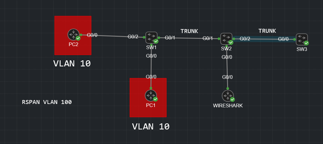
What happens if there are 3 switches? In other words, lets say that the source interface we want to monitor is on SW1, then we would simply execute the following commands on SW1 as the lesson describes.
But lets say SW2 is in the middle, what would we have to configure on SW2? Would we have to configure anything on SW2 at all other than the remote-span VLAN? I’m guessing not because the traffic would just pass through VLAN 100, is that correct?
If you have one or more intermediate switches between the switches that have the source and destination interfaces configured on them, then you must manually define the RSPAN VLAN on all those intermediate switches, and you must allow that VLAN on the trunks that connect the switches. In addition, you must issue the following command on all intermediate switches:
Switch1(config)# vlan 100
Switch1(config-vlan)# remote-span
Switch1(config-vlan)# end
You would then need to allow VLAN 100 on the trunk ports that connect to the source and destination switches. The reason for this is that RSPAN VLANs are specialized VLANs that behave differently than other VLANs. For one thing, they don’t perform any MAC address learning. Secondly, they can only be assigned to trunk ports and not access ports. And thirdly, this way you ensure that all captured traffic, including control frames, are successfully sent through the network to the destination SPAN port.
You completely lose its configuration. In the output of show vlan brief, it doesn’t appear in any VLAN at all until I remove this SPAN configuration. Do we know what’s happening in the background with this port? From what I understand, without further configuration, it cannot even receive regular data and its sole purpose is port-mirroring which makes sense since you’d only want mirrored traffic on that port and not any traffic that the WIRESHARK PC actually sends.
Now, I am wondering. The remote-span command under VLAN configuration mode basically tells the switch that this VLAN is for the purpose of RSPAN/Port Mirroring. So if you specify it in the monitor session configuration but forget to configure it as one under VLAN configuration mode, it basically won’t mirror anything towards the desired destination port.
Next question, if you configure a port to be part of the RSPAN VLAN, it basically ends up being disabled and would not be used for forwarding data, right?
SW1(config)#interface G0/2
SW1(config-if)#switchport access vlan 100
*Mar 10 10:24:06.571: %PM-4-INACTIVE: putting Gi0/2 in inactive state because access VLAN is remote SPAN VLAN
Two more questions. In my topology, SW2 is sending the traffic towards the WIRESHARK PC but also towards SW3. Is this the desired output?
//Edit: On trunk ports, it might also be a good idea to restrict where this VLAN is allowed, considering that the traffic will literally be sent out of every trunk port
Yes, that is the case. Once a port is configured as a destination port for SPAN, it cannot be used as a normal port. It doesn’t accept incoming frames, indeed it will drop them completely. It only regenerates whatever traffic it sees on source ports and sends it out to the Wireshark PC (or any other packet capture utilities).
Yes that does seem to be the case. Cisco recommends that the RSPAN VLAN be configured and up and running before RSPAN source and destination sessions are configured.
Yes, that is the case, and it is confirmed by the syslog message you see in your output.
This happens because the RSPAN VLAN is included in the trunk. Make sure (as you have already suggested in your post) to restrict the RSPAN VLAN only to switches and trunks that you need it, otherwise it can result in A LOT of unwanted traffic being forwarded to various areas of your network. If you’re using VTP, you can prune RSPAN traffic on trunks to prevent this, but if VTP is not running, you have to do this manually.