Hi rene, i don’t understand this ip route 3.3.3.3 255.255.255.255 192.168.23.3 but your next hope is r2..did you use recursive static route in this scenario ?
Hello Anas
Yes, you are correct, Rene has configured a recursive static route. When a packet with a destination address of 3.3.3.3 is to be sent, this routing table entry is matched. However, the next-hop IP of this entry (192.168.23.3) must then be reachable as well, so a recursive lookup of that address takes place. The appropriate route is matched, with a next-hop IP of 192.168.12.2 which is R2, and the packet is sent.
For more information on recursive routing, take a look at this NetworkLessons Note on recursive routing.
I hope this has been helpful!
Laz
thank you for the lesson; one question what is the difference between VPN and secure tunneling you just introduced?
Hello Berthol
A VPN is a general term used to refer to a mechanism that establishes a secure connection between two remote sites over an insecure network like the Internet. More about VPNs, in general, can be found at this NetworkLessons note on VPNs.
This particular configuration in the lesson is a type of VPN. A VPN in essence is a tunnel, but this lesson shows how to implement a VPN using specific protocols and mechanisms including an IPSec tunnel.
It really simply has to do with terminology and the context in which it is used.
I hope this has been helpful!
Laz
Hello, I have a question. Therefore, when building site to site IPsec, both private and public networks are entered into the same routing protocol. Then it can be private networks be exposed to the outside world?
Hello Yuchan
When building a site to site VPN using IPSec Tunnel, the private IP addresses used internally in the remote networks are kept separate from the public IP addresses used over the intervening Internet. This is part of the functionality of a VPN.
In this particular lesson, Rene chose to use addresses in the private range to represent the interconnection between R1 and R3. The following diagram reimagines the topology using address ranges that resemble a situation where you are routing the IPSec tunnel over the Internet:
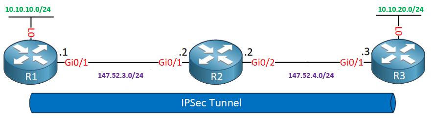
The green addresses are private while the purple are public. The IPSec Tunnel will tunnel only private addresses.
Now indeed, both R1 and R3 will have both public and private addresses entering the same routing protocol, assuming you have configured a routing protocol here. That does not mean private networks will be exposed to the public Internet. For communication between R1 and R3, the crypto access list is used to match traffic, encrypt it, and direct it through the tunnel. For traffic that does not match, typically in a real-world scenario, such traffic would be NATted to gain access to the Internet.
I hope this has been helpful!
Laz
1 Like
Hello Laz!
I just wanted to verify that I am understanding the encapsulation that takes place whenever a packet matches the access list configured on the crypto map in R1.
Since we are using tunnel mode with ESP, that means we are encapsulating the original packet that matched the crypto map inside a new packet with a new IP header that will use the IPSEC tunnel peer’s IP’s as the source/destination IP addresses. In this case that would be a packet with a source IP of 192.168.12.1 and a destination IP of 192.168.23.2 if any traffic being routed by R1 matches the crypto map, such as a ping with Destination IP of 3.3.3.3 and source IP of 1.1.1.1.
It is due to that encapsulation that R2 knows how to forward those packets to the loopback of R3 without needing any routes configured towards that loopback correct? Since R2 has directly connected networks for 192.168.12.0/24 and 192.168.23.0/24, when a packet with a destination IP address matching any of those networks comes into the router, It knows how to forward those encrypted packets without having to look at the inner IP header that actually has the destination IP of 3.3.3.3 and source of 1.1.1.1.
But, since R2 doesnt have any routes configured for the loopbacks of R1 and R3, any packet with a destination IP of either of those Loopbacks will be unrouteable by the router and the packet would be dropped since it doesnt have any entries that would match a destination of 3.3.3.3 or 1.1.1.1. Because of this, in the example for the lesson where we pinged 3.3.3.3 from R1, if we had not used the source command to specify our loopback IP as the source IP address of the packet, the ping would have failed. This would be due to the packet not matching the crypto map access list, and thus not being encapsulated into a ESP IP header that R2 would know how to route (via its directly connected network routes). Therefore, for the network shown in this lesson, in order to have any connectivity between the loopbacks of R1 and R3 those packets would have to be encapsulated using the ESP IP header after matching the crypto map access list, otherwise R2 would need to have routes configured on it that would enable it to find a match for any packets with destination IPs of 1.1.1.1 or 3.3.3.3. Is my understanding correct?
As a final question, is the access list configured on a crypto map only used to match the traffic that should be encrypted, and traffic that should not be encrypted? for example, will an access list configured on a crypto map drop any traffic that does not match the statement, or simply not encrypt it? in the example for the lesson, we only use a permit statement for packets being sent between the loopbacks, but does an access list on a crypto map not have an implicit deny everything at the end like a regular access list does?
Thank You Laz!
Hello Paul
Your understanding of how ESP encapsulation works in tunnel mode is correct. The original IP packet is encapsulated in a new IP packet with new source and destination IP addresses. This is what allows R2 to forward the packets to R3’s loopback without needing any specific routes configured for that loopback. R2 will simply forward the packet based on the outer IP header, which contains the IP addresses of the IPSec tunnel endpoints, and R2 has routing information for those networks.
You’re also correct in stating that if R2 does not have routes to the loopbacks of R1 and R3, it will drop any packets with those destination IPs. This is why the source IP must be specified when pinging from R1 to 3.3.3.3, to ensure the packet matches the crypto map and gets encapsulated.
Concerning your final question, the access list on the crypto map is used only to identify interesting traffic, that is, traffic that we want to encapsulate. The ACL doesn’t act as a filter that will permit or deny traffic, but it acts as a mechanism to identify traffic to encapsulate, and traffic not to encapsulate. Traffic that does not match the ACL is not denied, it is simply sent without encapsulation. Does that make sense>?
I hope this has been helpful!
Laz
Hello Laz and Rene.
If you have access to Cisco CML, could you please verify whether you can configure IPSec via crypto maps? I’ve created a topology identical to this one, yet I could not get my configuration to encrypt any traffic, the tunnel didn’t even form.
I’ve even copied the configuration and checked everything and yet my configuration never worked when I used crypto maps (as opposed to the VTI approach).
Thank you.
David
Hello David
I went into the lab and powered up a IPSec tunnel mode lab and it seems to be working fine. THe topology is a bit different:
H1 – R1 – R2 – H2
Here R1 and R2 are playing the role of the tunnel endpoints and we have separate hosts pinging each other rather than looback interfaces. Crypto maps were used to configure IPsec tunnel mode, and the tunnel seems to be working.
R1#show run | section crypto
crypto isakmp policy 1
 encr aes
 authentication pre-share
 group 2
crypto isakmp key MY_PASSWORD address 10.10.10.2
crypto ipsec transform-set MY_TRANSFORM_SET esp-aes esp-sha-hmac
 mode tunnel
crypto map MY_CRYPTO_MAP 10 ipsec-isakmp
 set peer 10.10.10.2
 set transform-set MY_TRANSFORM_SET
 match address 100
 crypto map MY_CRYPTO_MAP
R1#show crypto session
Crypto session current status

Interface: GigabitEthernet0/2
Session status: UP-ACTIVE
Peer: 10.10.10.2 port 500
  Session ID: 0
  IKEv1 SA: local 10.10.10.1/500 remote 10.10.10.2/500 Active
  IPSEC FLOW: permit ip 192.168.1.0/255.255.255.0 192.168.2.0/255.255.255.0
        Active SAs: 2, origin: crypto map
R1#show crypto ipsec sa | include caps
    #pkts encaps: 4, #pkts encrypt: 4, #pkts digest: 4
    #pkts decaps: 3, #pkts decrypt: 3, #pkts verify: 3
R1#
Can you share some more info with us so that we can help you further troubleshoot? Let us know how it goes!
I hope this has been helpful!
Laz
Hi, Rene
I got an interesting question for you.
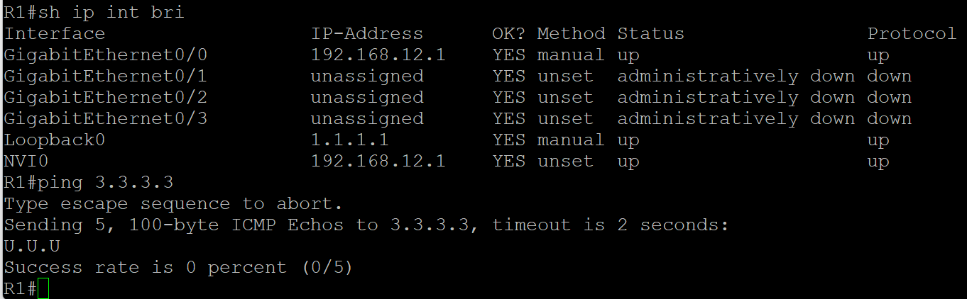
When I input the cisco command: no ip route 3.3.3.3 255.255.255.255 192.168.23.3
and retype this command again
at the command, I found I cannot ping 3.3.3.3 successfully from R1.
as the pic below shown
could you please help analyze the root cause for this issue?
is there anything important that I missed?
Hello Galen
What you see is actually expected. Let me explain. If you look at the lesson, you will see that the crypto ACL on R1 is:
access-list 100 permit ip host 1.1.1.1 host 3.3.3.3
That means that only traffic with a source of 1.1.1.1 and a destination of 3.3.3.3 will be matched as interesting, and thus encrypted and sent through the IPsec tunnel. When you issue the ping 3.3.3.3 command, your source is chosen by the router to be the IP of the exit interface from which the ping is sent, which is 192.168.12.1. This source does not match the crypto map and is thus not interesting traffic, and so it is not encrypted, nor is it passed through the tunnel.
The packet is simply forwarded as a normal packet using only the routing table. Specifically, it uses the ip route 3.3.3.3 255.255.255.255 192.168.23.3 entry. This causes a recursive lookup where the 192.168.23.3 destination is looked up, and an entry is found, which is via R2. However, when the packet reaches R2, R2 has no idea how to get to 3.3.3.3 so the ping fails. (you get those “U” indicators which is an ICMP unrecahble message.)
In order to test the IPsec tunnel, you must ping with a source of 1.1.1.1 and a destination of 3.3.3.3. Only then will you confirm that your VPN is working. So I believe the removal and the reinstating of the route you mention initially does not affect the VPN tunnel, and you can confirm this by attempting the ping as I suggested. Try it out and let us know how you get along!
I hope this has been helpful!
Laz
why when configuring the static route we are using two commands:
R1(config)#ip route 192.168.23.0 255.255.255.0 192.168.12.2
R1(config)#ip route 3.3.3.3 255.255.255.255 192.168.23.3
why not just say..
R1(config)#ip route 3.3.3.3 255.255.255.255 192.168.12.2
in your example on R1 you used the Tunnel 0 in the static route as next hop
ip route 192.168.2.0 255.255.255.0 Tunnel0
can we use instead the tunnel ip as next hop like this
ip route 192.168.1.0 255.255.255.0 12.12.12.2
and if yes what is the difference between both
Hello Tony
I’ll respond to both of your messages in one post.
There are two commands there because we need R1 to know how to get to both the 192.168.23.0/24 and the 3.3.3.3/32 networks.
The first command enables R1 to know how to get to the transit network (the link between R2 and R3), which also includes the 192.168.23.3 IP address, which is the other end of the IPsec tunnel. Without that first command, any packets destined for the 192.168.23.3 destination (such as those used by the tunnel formation mechanism) will be dropped, and the tunnel will not form.
Now the second command could be replaced with the one you suggest, and the network would function. Either 192.168.12.2 or 192.168.23.3 can be used as a next hop for that, it will work in both cases.
This question has to do with the IPSec static virtual tunnel interface lesson.
You could issue the command that you suggest. The result would be a recursive lookup. The next hop IP address of 12.12.12.2 would be looked up within the routing table. There should be an entry there that says that that network is directly connected to the Tunnel0 interface, thus it would be routed out of there. So the result is the same, but two lookups would take place in order to achieve the same thing.
I hope this has been helpful!
Laz