I’m so glad to see that you’re doing your best to develop your course website - it’s realy nit and I could already prepare for the new CCIE Infrastructore exam through your site.
I’d like to know why the NTP course lack so much of the basic information regarding stratum , ntp message types and values , what is ntp master / ntp server and the difference between those?
the requirement of the multicast address 224.0.1.1 which is uniqe for the ntp operation.
the requirement of the address 127.127.1.1.
what is SNTP?
who is startum 0 , and when we will see it.
There is lot of basic information that lack in the course and I couldn’t find anywhere on your courses, may I ask why is that?
Thanks you very much , I think the ntp topic is realy important and unclear to a lot of people especially me after learning the basics about 6 times and I still can’t say that I master this protocol.
I will attempt to answer some of your questions here, and have Rene respond to your more general question about the content.
The ntp master command is used to configure a device as a clock to which its peers can synchronize. In other words, this command makes the device an NTP server.
The ntp server command is used on the client to indicate with which server its time should be synchronized. It is followed by the IP address of the NTP server (master).
224.0.1.1 is a reserved multicast address used by NTP. If you configure NTP to use multicast, it will send its updates using this destination multicast address. All NTP clients will listen on this multicast group for all NTP syncrhonization tasks. Multicast for NTP is enabled on a per interface basis.
As for the 127.127.1.1 address, you will see this as the address of the NTP association on a device which is using its own internal clock for synchronization. For example:
This shows that this router is not syncing with other devices, but is using its internal clock as the time source.
Simple NTP is a less complex implementation of NTP which uses the same protocol, but it doesn’t require a storage of detailed history of NTP events over time. It’s often used in hardware systems and applications where full NTP is not necessary. You can find out more about it at RFC 4330. More info about how it can be configured on Cisco devices can be found here:
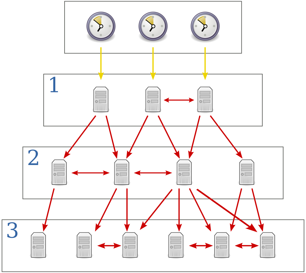
A Stratum 0 NTP device, also known as a “reference clock” is a highly accurate time keeping device (such as an atomic clock, a radio clock, or a GPS clock) that generates a very accurate pulse signal which can be used to measure time extremely precisely. Stratum 0 timekeeping devices are not connected directly to the network. They are connected directly to computer systems physically in the same location, that syncrhonize their time with the Stratum 0 devices. These computer systems are considered Stratum 1. These Stratum 1 computers in turn connect to the network, the Internet, and to all subsequent stratum devices. Look at the following diagram:
The top row is stratum 0, which are directly connected (yellow arrows) to stratum 1 computers, which are network-connected (red arrows) to the rest of the networks.
It’s been awhile since I wrote this lesson. Back then, I think I did it for the CCIE lab exam which focuses on the configuration, not so much on what happens behind the scenes. Creating another lesson which covers NTP in detail might be a good idea.
I created an idea on our feedback board and added you as a voter:
Try it out with real devices if you can, and let us know your results.
Not sure what you mean by ATM. I’m assuming you mean stratum 0 atomic clocks? If so, you will never have direct access to stratum 0 devices. Remember, these connect directly (physically in the same room) with stratum 1 computers with specialized connections. The stratum 1 computers are then accessible to the Internet and to your networking devices. There are several stratum 1 NTP servers that are open for use by anyone. You can see a list at the official Network Time Protocol website.
Some serve specific areas, while others serve the whole world. The closer physically that you are to the one you register to, the more accurate your syncrhonization will be.
Everything is working, except from multicast, there are no packets between SW1 and R5. When I try debug NTP it shows me.
Apr 10 12:30:44.077: NTP message sent to 239.1.1.1, from interface 'Vlan10' (192.168.10.1).
Apr 10 12:30:44.078: NTP IPv4 multicast message discarded: not an NTP multicast client for 239.1.1.1
I don’t know why this is happening, configuration looks good.
I managed to test the multicast option in my real lab and it is working fine on my routers , however, my switches configured on vlan 222 with ip address , and when I set one of them as the client and the other as the master , it doesn’t seems to work.
I configured the switches with NTP on the vlan interface 222 , couldn’t configure NTP on L2 interfaces which connects between the two switches.
Do you know how I can configure the NTP multicast on the switches? I tried using debug but nothing appears on the cli (used terminal monitor as i’m remotely connected to the devices).
However the static NTP server configuration seems to be working fine on the switches , only multicast and broadcast aren’t wroking as I mentioned.
There is no reason for multicast not to function on switches, as most IOS switches do support this NTP feature. However, it may be that the particular IOS or platform does not support this particular function. I suggest you first check your configuration, with the help of Cisco command line references for ISO switches and NTP, as well as checking your particular IOS/platform compatibility with NTP features using the Cisco feature navigator.
It seems like one of my switches was using ntp version 4 (the client) while the master used version 3.
After changing my client to use version 3 either it finally starts to listen to the broadcast messages and the clock synchronize - which means version 4 isn’t capable with version 3, or maybe its only half capable if the master is version 4 and the client is version 3, but not the opposite.
That’s interesting. I did a bit more research about the compatibility between v3 and v4, but didn’t find anything that says they’re incompatible when using multicast. The only indication of a problem when using v3 with v4 is when IPv6 is used.
In any case, thanks for sharing that, it’s an interesting and useful piece of information!
Could you clarify what is the use of ntp access-group peer 1 on router and ntp access-group peer 3 on switches , how are we choosing the peer numbers and when they are different and when same( like on switches ) ?
These commands reference access list numbers. In the first case, an access list with number 1 is created, and that is what is referenced in the ntp access-group peer 1 command. In the case of the switches, an access list with the number 3 is created, and this is what is referenced in the ntp access-group peer 3 command.
The numbers that are chosen are arbitrary. Remember that standard access lists can have numbers between 1 and 99 while extended access lists can have numbers between 100 and 199.
Typically, you should configure one or two central devices to sync with an external NTP server on the Internet. These should act as your internal NTP servers. All the rest of your internal devices, should synchronize with your internal servers. The reason for this is, if connectivity to the Internet is lost, all devices will lose connectivity to the NTP server, and are in danger of losing synchronization. However, if you configure it as I describe above, even if you lose internet connectivity, at least the internal synchronization between devices will not be lost.
If I config ntp master 8 in one router and this router cannot find any server with stratum less of 8, it will synchronize with its own clock or still can synchronize with a server with stratum higher than 8? Can you help me with this question? Thanks in advance!!
Yes, that is correct. If you configure a device as master with a stratum of 8, then it will only synchronize itself with other devices of stratum 8 or lower. Remember that the stratum system is used in something like a spanning tree, so that there are no syncrhonization loops taking place. This configuration simply says that the device considers its own internal clock “closer” to a stratum 0 device than any device with a stratum value higher than its own.
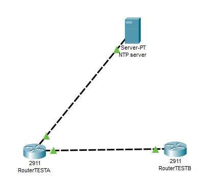
However Router B (which I’ve configured to use Router A as the NTP server) things look a bit weird:
The Stratum I would have expected to be 2 (since it’s one more hop away from the NTP server), however it’s showing as 0. And the Reach is showing as 0, even though the time is synced.