It looks like router B has not synchronized, since it is still in the INIT state under the ref clock heading. You can also see that the reach is 0 which means it hasn’t received any NTP packets, and the disp. is also very high. All of this seems to indicate that it has not successfully synced with the server.
The strange thing is that it does show a stratum of 0 and a * at the beginning, which seem to be contradicting the rest of the data.
I suggest you troubleshoot NTP connectivity to the server, and once you get connectivity, I believe the issues will be resolved. Take a look at this Cisco documentation, as it may be helpful to you.
Hello guys,
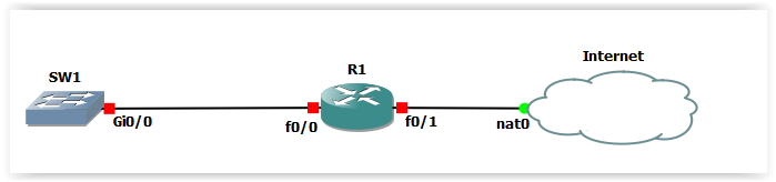
I would like to know whether it is possible to setup NTP via DHCP. I am using simple topology as below where R1 is setup as NTP server and is getting its time from pool.ntp.org. There is DHCP pool on R1 which provides IP address for LAN (where SW1 resides). Quick google says that there is Option 42 in DHCP - this option carries the NTP servers used on the network. I configured “option 42 ip 192.168.10.1” - 10.1 is IP on R1 fa0/0. IP address on SW1 was assigned via DHCP but not the time.
The configuration of the DHCP server to send option 42 is quite simple, as you have configured it. However, how a client receives this information depends on various factors. For Cisco devices, if you configure them as DHCP clients, not all IOS versions support the use of Option 42.
For example, according to this Cisco Community Thread, TAC (Cisco support) seems to have responded that IOS 15.2(2) doesn’t support option 42 as a DHCP client.
Now in order to receive the appropriate DHCP option, you must use the ip dhcp client request command in configuration mode of the interface which you are configuring as a DHCP client. Looking at a Cisco CSR running 15.7(3) as an example, I get the following options for this command:
R1(config-if)#ip dhcp client request ?
  classless-static-route       Classless static route (121)
  dns-nameserver               DNS nameserver (6)
  domain-name                  Domain name (15)
  netbios-nameserver           NETBIOS nameserver (44)
  router                       Default router option (3)
  sip-server-address           SIP server address (120)
  static-route                 Static route option (33)
  tftp-server-address          TFTP server address (150)
  vendor-identifying-specific  Vendor identifying specific info (125)
  vendor-specific              Vendor specific option (43)
  <cr>

R1(config-if)#
Notice that none of them are NTP option 42, so it seems this device and IOS don’t support it.
For Cisco IOS XE 16.11, this Cisco documentation seems to indicate that it is supported, as it gives you the option of specifying DHCP option 42.
In any case, you will have to see the platform and IOS version of the switch, and see if it accepts the DHCP option for NTP.
I have a question about NTP.
If the NTP server is in a different timezone.
And you use this NTP server on your switch to sync the time.
Is that going well or do you need to do additional configuration?
So that logging timestams and the clock are the same?
Authoritative NTP sources that are found on the Internet always use Coordinated Universal Time (UTC) regardless of where on Earth they are located. UTC is essentially the same as Greenwich Mean Time (GMT).
Each Cisco device that wants to synchronize with an NTP source is configured with the timezone in which it is located. (By default, the timezone is set to UTC). Now you can configure the timezone using the clock timezone command. Whenever a Cisco device synchronizes with an NTP source, it makes the necessary adjustments to the time to ensure the correct time zone is calculated. For this reason, it is important to correctly configure the timezone so that the NTP synchronization is done correctly.
More information about this command can be found here:
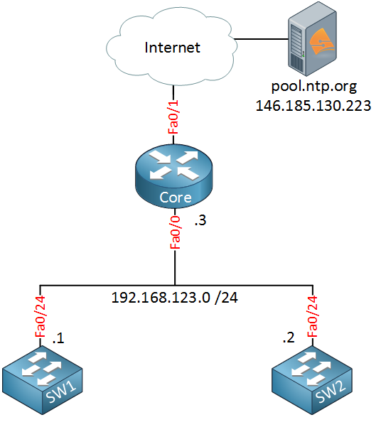
…it simply means that the Fa0/0 interface on the Core, and the Fa0/24 interfaces on the switches are on the same subnet. You can imagine that an unmanaged switch exists there connecting all three devices to the same broadcast domain/network segment. As you can see, all of the interface IP addresses indicate that they are indeed on the same subnet.
thanks for the comment ,
i tried to build the topology again but it doesn’t match to the output of the configuration of the devices in my topology ,
im also tried to work on the HSRP lab and i didn’t understand what to configure when there R1 device in there ,
if there’s any option that you can send the lab’s so i can see how it look like or another option that you think of that would really help.
Most lessons have a section where you can see the configurations used by Rene. You can use those as a guideline to create your topologies and configure your labs. If you have specific questions about the labs, about particular commands or behaviors that you experience in your topology, please share them in more detail so we can help you specifically.
you dont need to make Core Router as NTP server (with ntp master command) to the SW because you are pointing from it to an NTP server already (pool.ntp.org) ?
If you were not pointing to another NTP server you need to make it NTP server to be able to serve NTP to the clients (switches) ?
When you configure a network device, such as the Core Router in this lesson, to operate as an NTP server, you don’t actually have to explicitly configure it as a server. The fact that the switches are configured with the command ntp server 192.168.123.3 makes the Core Router the NTP server, and the switches the NTP clients.
The ntp server pool.ntp.org command configured on the Core Router actually makes this device an NTP client to the pool.ntp.org server, but at the same time it retains the role of NTP server for the switches.
Now the master command is simply used to let a device know to consider its own clock as valid, and it is also used to manually set a stratum number for this NTP source. This way, clients of this device will adopt their stratum number based on the locally configured one. This type of configuration means that no external NTP sources are used for synchronization.
following the below attachment topology i am not able to make r2,r3 to be synchronized on gns3? any suggusetion? i tried almost all the combinations, sw3 point to r1 , then the remaining switches point to the others… , r1 as master, nothing again, then peering nothing…
There may be many different reasons for synchronization not taking place in an NTP environment. Although I am not able to take a look at your particular topology, you can use some of the principles found in the following comprehensive Cisco troubleshooting guides for NTP:
Now having said that, some of the most common issues that involve NTP include connectivity, stratum numbers too high, or misconfiguration with clock time zone or clock summer time commands.
Go through the troubleshooting process and let us know how you get along. Share some of your debugs and outputs with us so we can help you further if you have not resolved the issue.
Hi!
In the current network I support, all Cisco devices (routers, switches, and firewalls) point to the domain controllers (Windows NTP server) to sync time. Now that we are hardening our posture to be more aligned with security best practices, we must configure NTP authentication keys on every network device so that the communication between the NTP client and server is authenticated. Is it possible to achieve md5 authentication on the Windows NTP server between Cisco devices? If so, how do you configure the md5 key on the windows server?
After doing a bit of research, I have found that, unfortunately, the Windows NTP server, which uses Windows Time Service (W32Time), does not natively support MD5 authentication for NTP as Cisco devices do. If you want to use MD5 you will have to look for another NTP server solution such as using a Linux server with the NTP daemon “ntpd.”
Is CML completely broken when it comes to configuring NTP?
R3(config)#do show ntp ass

  address         ref clock       st   when   poll reach  delay  offset   disp
*~62.168.94.161   17.253.14.253    2     39     64     1 22.926 146422. 188.49
+~193.87.160.18   217.31.202.100   2     40     64     1 23.925 146423. 188.48
 * sys.peer, # selected, + candidate, - outlyer, x falseticker, ~ configured

R3(config)#do show ntp status
Clock is unsynchronized, stratum 3, reference is 62.168.94.161
The first command clearly shows that R3 is synced with the first NTP server while the second command says the opposite.
And after a while, it just breaks completely
R3(config-if)#do show ntp ass

  address         ref clock       st   when   poll reach  delay  offset   disp
 ~185.242.56.3    217.31.202.100   2     48     64    17 28.629 9569.43  0.862
 ~87.197.160.189  217.31.202.100   2      9     64    37 37.338 10694.8  0.945

R3(config-if)#do show ntp stat
Clock is unsynchronized, stratum 16, no reference clock
Also, NTP takes around 15 minutes to synchronize in CML which is very long for me, especially when I want to try out different configurations and test different behaviours. Is there no way to speed this up?
Indeed, according to Cisco’s official documentation the “*” does mean “synchronized”. The Cisco documentation I am referring to shows this output along with a different legend:
Note the * master (synced) indicator. In the output in your post however, the * refers to a system peer. So I believe that this distinction is important in understanding your results.
Because I have been unable to find documentation that matches your CML output (which I have confirmed in the lab BTW), my personal hunch is that in your CML scenario, the * simply means “selected” just like the “+” indicator in Cisco’s documentation. By this logic, the * only indicates that this NTP server has been selected as the system peer, meaning the router intends to synchronize with it, but is not necessarily synchronized.
Now this seems to be supported by the fact that the show ntp status command shows that you are unsynchronized. Let’s examine why this could be.
Well, we see a very high offset value of 146442 ms. This means there is a significant time difference between your router and the NTP server. This prevents synchronization because NTP will gradually adjust the clock instead of making sudden jumps. This may also explain why you are experiencing a long time for synchronization to take place.
You can also see that the reach value is only 1 which means that only the last single poll of the server was successful. The reach value is in octal (base 8) which means it can only have the following values with the following meanings:
0	00000000	No response from server
1	00000001	Only the last poll succeeded
3	00000011	Last 2 polls succeeded
7	00000111	Last 3 polls succeeded
17	00011111	Last 5 polls succeeded
37	00111111	Last 6 polls succeeded
77	01111111	Last 7 polls succeeded
377	11111111	All 8 most recent polls succeeded
Now in your second output, you can see a reach value of 17 which means that the last 5 polls were successful, and you can also see that the offset has been reduced which is expected. But it seems that it was too much for NTP, and it simply stopped trying.
I suggest you attempt it again, and try to manually configure the local clock to be closer to the NTP server’s time, so the offset will be smaller and it will synchronize faster. Also ensure that you do indeed have connectivity to the NTP server, and check the reach value to ensure consistent connectivity.
I hope all of this will help you in your troubleshooting. Let us know how it goes!