This topic is to discuss the following lesson:
Hi Rene,
Thanks for your video. What if I want a hub and spoke topology, but I still want a communication between the Spokes (Through the HUB).
In this example we see that the communications between spokes is now impossible.
Thanks
Nicolas
Hello Nicolas
I think there may be confusion as far as what we mean when we say hub-and-spoke.
The default behavior of an SD-WAN topology is full mesh. This means that all sites can communicate with each other directly. The hub and spoke topology that Rene mentioned in the lab refers to the restriction of allowing each vEdge to communicate ONLY with the central site, and not communicate with any other vEdge device. This is not to be confused with hub and spoke topologies such as DMVPN for example.
What you are suggesting is a third option of operation, which is to force the SD-WAN topology to function as a hub-and-spoke topology and have all communication between sites routed through the hub site rather than directly between vEdge devices, correct? Kind of like a DMVPN Phase 1 situation.
You can direct traffic within the SD-WAN topology to force it to behave in a hub-and-spoke manner using various methods including the VPN topology configuration, routing, data policies, as well as policies that manipulate OMP route advertisement to influence the SD-WAN overlay. SD-WAN was not designed for this, but it can be done. What method you choose really depends upon what you want to achieve.
The question I have however is why would you want to do this? The purpose of this particular lesson is to restrict communication between vEdge devices, not to actually create a hub and spoke topology where traffic is routed through the hub. If you can answer the why, then we can then move on to further discuss the appropriate solution.
I hope this has been helpful!
Laz
1 Like
Hello Laz,
Thank you for this detailed answer.
Imagine I have only MPLS underlay with different SP (many MPLS SP) tow sites each attached to an MPLS SP that need to communicate together through the hub (that have connectivity to both MPLS SP must be able to receive the routes of each other’s for example. Adding a default route could be a solution right?
Thanks ![]()
Nicolas
Hello Nicolas
OK I understand. So by design, your initial “underlay” network is such that there are parts of the network that can’t communicate directly. So you have multiple MPLS service providers, and you have a particular site that is connected to two (or more) MPLS networks that acts as the “hub” for communication between entities in those MPLS networks.
So if you have topology where two vEdge devices cannot communicate directly over the underlay due to the restrictions you describe, but can each communicate with the main site where the controllers are hosted, the Cisco SD-WAN fabric will inherently handle the situation to a certain extent. The system’s OMP and TLOC properties will play a role in determining viable paths.
If direct communication between two vEdges is not possible due to underlay restrictions, the tunnel establishment will fail. However, even if a direct path isn’t available, the vEdge devices are aware (thanks to OMP and TLOC information) of other vEdges they can communicate with. In your scenario, both restricted vEdges can communicate with the main site. Thus, when they need to exchange data, the traffic will inherently use the main site as a relay point since a direct path isn’t viable. This is part of the SD-WAN’s inherent path decision mechanism.
So based on the OMP path attributes, the vEdge will choose the best available path. If the direct path is unavailable, it will select another path, like through the main site.
I hope this has been helpful!
Laz
Hello,
Thanks for the lesson, but I do have a doubt. I am labbing a HUB and Spoke topology on SD-WAN and I am having a hard time on the design. Here is my idea:
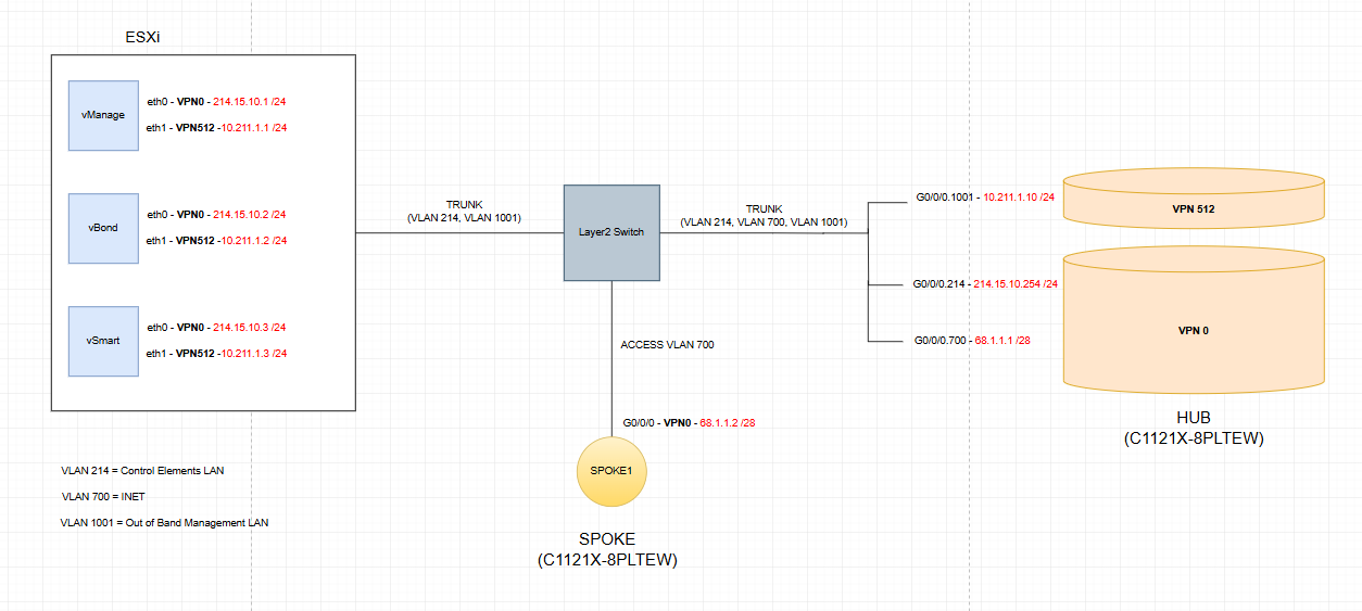
I can get the HUB up on the SD-WAN fabric overlay, with all control connections successfully established. But when I get into the SPOKE, I ran into the folloeing issue:
- The Spoke router can ping 68.1.1.1 (the HUB) and also 214.15.10.254 (G0/0/0.214 on the HUB), but I cannot ping the vBond or non of the control elements from the Spoke.
- Same applies viceversa, I can ping 68.1.1.1 from the control elements but not 68.1.1.2 (the Spoke). Why?
I configured a default static route pointing to 68.1.1.1 on the Spoke router. I was expecting the simplest routing: the Spoke tries to reach 214.15.10.2 (the vBond) and the packets get to the HUB (which is happening). Then the HUB sees that the destination of the packets is directly connected and proceeds to route them. Why is this not happenning, if both subinterfaces are on the same VPN - VRF?
I appreciate any help, I have stuck with this for many hours. Thanks,
Jose
Hello Jose
I can give you some guidelines that will help you in your troubleshooting process, and hopefully get you unstuck from your hours of searching.
Short answer: you’re trying to hairpin controller traffic through a WAN Edge, and that won’t work the way a normal router would. In Cisco SD‑WAN, controllers must be reachable from each WAN Edge directly over the transport (VPN 0). A WAN Edge is not a general-purpose transit router in VPN 0, so it won’t route and forward your spoke’s underlay traffic to a service-side controller that’s behind or reachable through the hub. Let’s analyze each communication:
- Spoke can ping 68.1.1.1 (hub) because that’s the hub’s transport IP (VPN 0) and the two WAN edges have underlay reachability.
- Spoke can ping 214.15.10.254 (hub subinterface) because that address is directly on the hub itself, so the hub can respond locally.
- Spoke cannot ping 214.15.10.2 (vBond behind the hub): the spoke forwards the packet to the hub in VPN 0, but the hub does not act as a transit router to forward VPN 0 traffic out toward a service-side network (or even between VPN 0 interfaces for transit). The packet dies at the hub.
- From the controller side, you can ping 68.1.1.1 (hub), but not 68.1.1.2 (spoke), for the same reason in the reverse direction: the hub won’t forward that controller-originated traffic across its VPN 0 toward the spoke.
All WAN edges initiate DTLS/TLS control connections to vBond, vSmart, and vManage from VPN 0 directly across the transport (Internet/MPLS/etc). The controllers must be reachable in the underlay. Do not place controllers behind a WAN Edge and expect other WAN Edges to reach them through the overlay or by transiting another WAN Edge’s VPN 0.
So what should you do? There are a couple of options, depending on if you want to simply lab it and get it working, or if you want to apply this to a production network:
Option A (best for production networks):
- Put the controllers on the transport so they are reachable from every WAN edge over VPN 0.
- Give controllers public/transport-reachable IPs, or
- Place them behind an underlay L3 device (not a WAN Edge) that provides routing/NAT so any WAN edge can reach them from VPN 0.
Option B (lab quick fix):
- Keep the hub WAN Edge as-is, but add a separate L3 router or a cloud segment at the hub site that routes between 68.1.1.0/24 and 214.15.10.0/24. Point the spoke’s default route to the underlay/cloud, not to the hub WAN Edge. The hub should not be the transit for controller reachability.
A couple of things to keep in mind:
- Don’t use a WAN Edge to forward transit traffic in VPN 0. VPN 0 is reserved for transport/TLOCs and control connections, not for general underlay routing through the edge.
- Do not place controllers in a service VPN (e.g., VPN 10/214) and expect edges to reach them via the overlay before control is up. It’s a classic chicken-and-egg problem. Control must come up first, via VPN 0.
Does that make sense? This should get you thinking about your topology and the possible changes you can make. Let us know how you get along, so we can help you out further if you need it.
I hope this has been helpful!
Laz
Thanks very much Laz, all clear now! However, I will like to point that:
Place them behind an underlay L3 device (not a WAN Edge) that provides routing/NAT so any WAN edge can reach them from VPN 0.
Careful with placing them behind a NAT device, specially all three elements sitting behind the same NAT, because problems arise since the vBond communicates with the other control elelments using their “inside” IP addresses and therefore that is the IP address that returns to each WAN EDGE attempting to join the overlay from the outside!! The Wan Edge gets an “inside” IP address of the control elements and therefore it cannot reach them!
But regarding the rest of the answer, thanks a lot, it saved a lot of troubleshooting hours!
Hello Jose
I’m glad it was helpful!! And yes indeed, you’re right, I appreciate you clarifying that. The idea was to place a device there that would perform the routing necessary to allow any WAN edge to reach the controllers from VPN 0. The possible use of NAT on that device was just an off the cuff mention of it. In any case you’re right, NAT is best avoided at that point!
Thanks again!
Laz
1 Like
Hello again,
I am labbing a topology with mutliple hubs for redundancy. I tuned the TLOC preference via a centralized policy to have the SPOKES prefer a specific hub based on their site-id. I also filtered all the SPOKE TLOCs so the only IPSEC tunnels are from SPOKE to HUB, there is no SPOKE-TO-SPOKE tunnels. All good. But now I have a doubt:
I want to configure end-to-end path tracking because if an indirect failure occurs, the spokes keep sending traffic to their preferred hub. I will like to use a TLOC Action type primary where I can set up multiple ultimate TLOCs so that if the vSmart detects that a HUB_1-SPOKE_X connection goes down, then it “tells” the remote spokes to not use HUB_1 anymore to reach SPOKE_X. I know this can be done with one ultimate-TLOC (for example, HUB_2 TLOC). But what if I add 2 more HUBS? Can I have 3 ultimate TLOCS? If so, how can I tune the order of failover? In my organization for example, we have 6 HUB routers and hundreds of spokes… so I will like to have the possibility of 5 failover HUBs (but each with a different preference) for every spoke in an indirect failure scenari.
Thanks,
Jose
Hello Jose
Oh this is getting good! ![]() This is really getting into the heart of multiple hubs and redundancy! Let’s take a closer look…
This is really getting into the heart of multiple hubs and redundancy! Let’s take a closer look…
To answer your question directly, yes, it is possible to have more than two hubs and to have multiple backup hubs for each spoke. This can be done by issuing multiple TLOCs in the tloc-action section of the policy.
policy
 centralized-policy POLICY_NAME
  data-policy DATA_POLICY_NAME
   vpn-list VPN_LIST
    sequence 10
     match
      source-ip SPOKE_X_PREFIX
     action accept
      set
       tloc-action primary
       tloc DEST_HUB_1_IP color mpls encap ipsec preference 1
       tloc DEST_HUB_2_IP color mpls encap ipsec preference 2
       tloc DEST_HUB_3_IP color mpls encap ipsec preference 3
       tloc DEST_HUB_4_IP color mpls encap ipsec preference 4
       tloc DEST_HUB_5_IP color mpls encap ipsec preference 5
       tloc DEST_HUB_6_IP color mpls encap ipsec preference 6
The preference (lower number is preferred with 0 the highest preference) here is used to allow you to choose the order in which the fallback process will choose the hubs.
Now you must keep the following in mind:
- You can have a maximum of 8 TLOCs per policy
- The more TLOCs you have the longer the convergence time
Let us know how you get along in your configuration!
I hope this has been helpful!
Laz
Some excellent resources that can help you out are the following:
Thanks Laz, all clear now!
1 Like
Hello Laz,
It is possible to use VPN 0 as a transit VPN so other routers can reach the SD-WAN Control Elements through it. I achieved it by using a loopback interface in unbound mode (in my case, since I had multiple transports but only one capable of reaching the SD-WAN Control Elements). Basically, what impedes using VPN0 as a transit VPN are the tunnel interfaces.
So if we use loopbacks as the tunnel sources and the physical interfaces as routable L3 interfaces, “routing” in VPN0 can be achieved and traffic destined from the transport MPLS (which does not have native reachability to cloud SD-WAN Control Elements) can get to the WAN Edge router, and get routed towards the SD-WAN Control Elements through a second physical interface connected to a second transport that has native reachablitiy to the SD-WAN Control Elements. Obviously, the SD-WAN Control Elements subnet must be advertised on the MPLS transport from the WAN Edge router that will make the transit happen.
In my case, I had 3 transports on the IR routers:
- public-internet
- lte
- mpls

The image shows the 2 IRs, which have the Internet tunnels sourced from Loopback110 and Loopback120 in bind mode to the SAME physical interface, and PBR is then configured on the ORs to provide tunnel / color consistency. The IRs also connect to an MPLS cloud using subinterface G1.170, and tunnel source Loopback170 in unbound mode, since I cannot bind the loopback to nothing because it will result in a conflict.
The Internet colors had native reachability to the SD-WAN Control Elements sitting on the same site as the IRs but on a DMZ. However, how can a WAN Edge router that only has the MPLS transport available join the overlay fabric? Or how can the vSmart receive the MPLS TLOC Routes if the MPLS transport cannot reach the public Internet and therefore, the SD-WAN Control Elements?
Well, I ended up advertising the SD-WAN Control Elements subnet from the IRs to the MPLS CE, and I sourced the tunnel using the mpls color from a loopback interface in UNBOUND mode, as well as the tunnels for lte and public-internet in BIND mode. Then, all 3 physical interfaces became routable interfaces, and good to go!
Hope it helps anyone with similar issues!
Hello Jose
Wow, thanks so much for your detailed explanation and sharing the results of your labbing with us!! You have implemented a very sophisticated and technically valid SD-WAN design using VPN 0 as an underlay transit network to enable MPLS-only WAN Edge routers to reach SD-WAN Control Elements (vBond, vSmart, vManage) through Internet Routers that have native Internet connectivity.
The fundamental mechanism that allows this to work is the decoupling of TLOCs from physical interfaces using loopback interfaces, and that’s the key! By sourcing tunnel-interfaces from loopback interfaces in UNBOUND mode, you “liberate” the physical interfaces to behave as standard Cisco IOS XE Layer 3 routable interfaces in VPN 0.
Thanks again for sharing this valuable and insightful information!
Laz
Hello Laz and Rene,
Here I am again stuck with another challenge: multicast in the overlay using the HUB as the RP and Route Replicator.

This is the extract of the lab that I am using to test multicast.
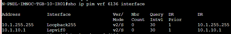
I configured the Data Center WAN Edge router as the RP and the Route-Replicator as well. I enabled PIM on Loopback255 only (on VPN 6136) on the Data Center. Then I enabled PIM on the interfaces of VPN 6136 of the branch routers.
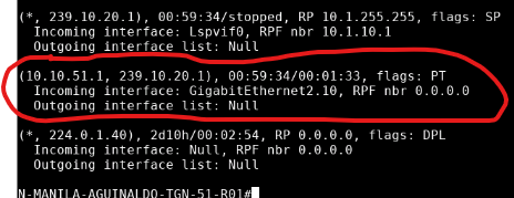
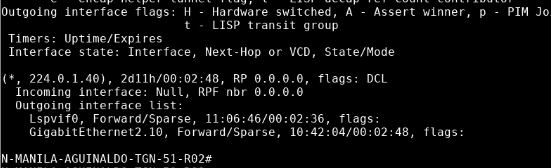
On the Branch 51 router 01, I get the traffic incoming on interface G2.10 and I see it on the Multicast Routing Table for VRF 6136:
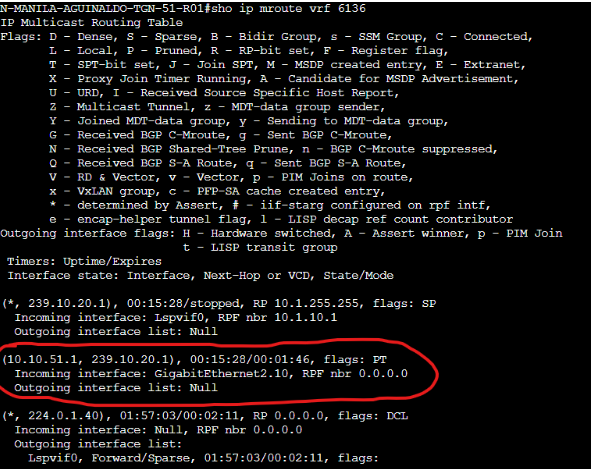
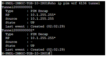
The Data Center Router is not receiving the PIM Register Messages from the router in Branch 51 because I can see encapsulation and decapsulation tunnels up on it, but no source for decapsulation: (on the Data Center router / RP)
So far so good.
On Branch 200, I subscribed a client to 239.10.20.1 and I can see that the mRIB reflects it too:
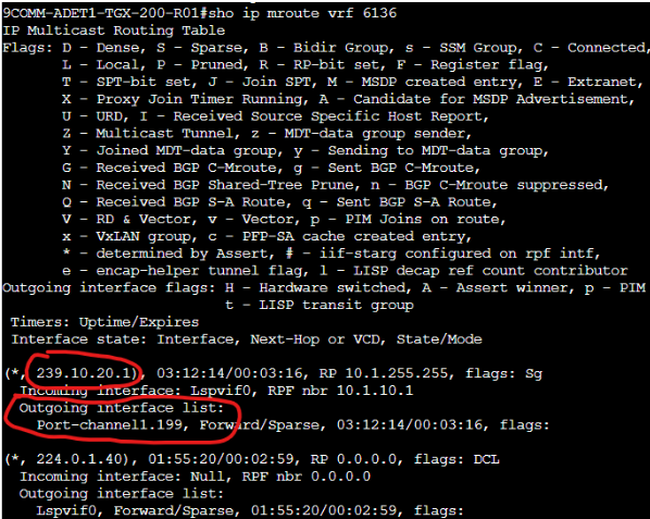
Now, the Branch 200 router sends the PIM Join message to the vSmart and here is the screenshot:
From here, I was expecting that the vSmart re-advertises this multicast route to the RP (the Data Center router) and then the RP builds the RPT and switches to the SPT after. However, something is not working in this process: the RP never builds the RPT and never shows any incoming interfaces for 239.10.20.1:
Now I was doubting if this is ever going to work: since the Data Center router is the RP and has no PIM Neighbors, technically the incoming interface is going to be the same as the outgoing interface… on legacy networks I solved this with PIM NBMA mode, but I was assuming that SD-WAN takes care of it automatically here. I see that SD-WAN creates on the background a “tunnel interface” to send/receive multicast traffic (Lspvif0):
on the Data Center Router:
And my question is: is PIM NBMA mode enabled on this “Lspvif0” interface? Is this interface configurable? Does it take care of the classic problem of the HUB being the RP and having to send/receive traffic on the same tunnel interface, which again, is a problem that is solved in legacy networking with PIM NBMA?
Thanks,
Jose
Hello Jose
Wow, that’s a nice setup, with multiple features being used. This is an excellent scenario that actually identifies a key architectural difference between legacy multicast over a DMVPN/mGRE hub and spoke topology, and multicast over SD-WAN. Let me directly answer your questions initially, and then take a look at some possible troubleshooting steps for your setup.
Q. Is PIM NBMA mode enabled on Lspvif0?
No. PIM is not configured or run on Lspvif0 at all.
Q. Is Lspvif0 configurable?
No. Lspvif0 (the Label Switched Path Virtual Interface) is an internal logical interface automatically created and managed by the SD-WAN software. You cannot and should not configure PIM parameters on it.
Q. Does SD-WAN automatically handle the hub-RP same-interface problem that PIM NBMA solves in legacy networks?
Yes, but not via PIM NBMA mode. It does it through a completely different architecture. SD-WAN solves this using OMP (Overlay Management Protocol) and the vSmart controller as a multicast route reflector, not by tweaking PIM behavior on tunnel interfaces.
SD-WAN with mutlicast has an important paradigm shift: PIM only runs on service-side (LAN) interfaces in SD-WAN. PIM does NOT run across the overlay between WAN Edge routers.
Here is an example of the control plane flow:
- Receiver (Branch 200): Host sends IGMP join for
239.10.20.1→ Branch 200 creates(*,G)PIM state locally → Branch 200 advertises this as an OMP multicast route to vSmart (not a PIM join across the overlay) - The vSmart plays the role of the Route Reflector Coordinator: It receives the OMP multicast join from Branch 200 → Reflects this to the configured Route Replicator (your DC hub)
- Route Replicator (DC Hub): Receives the OMP multicast route from vSmart → It should translate this into local PIM state so the RP sees receiver interest
- Source (Branch 51): Sends multicast traffic → Branch 51 FHR sends PIM Register (unicast) to RP → This traverses the overlay using normal unicast VPN routing
Now your RP showing no (*,G) or (S,G) state means the chain is breaking between steps 2 and 3.
Without knowing more about the configs, I can suggest a possible root cause for your issue.
Based on your symptoms, the most likely problem is an incomplete Route Replicator configuration on your DC hub. You must explicitly configure the multicast-replicator role on the DC WAN Edge. Just enabling PIM on Loopback255 is insufficient.
Secondly, you mentioned enabling PIM only on Loopback255. You also need PIM enabled on all service-side interfaces in VPN 6136 where multicast traffic will actually flow (not just the loopback). Here are some troublehooting steps that may help in resolving the issue…
- Verify Route Replicator Configuration on DC Hub: Check if multicast-replicator is enabled
- Check OMP Multicast State BEFORE Looking at PIM.
- ON the DC Hub (the RP/Route Replicator)
- If you see an entry for
239.10.20.1from Branch 200, then OMP is working, but translation to PIM is failing. - If you don’t see an entry, then the problem is at the vSmart or Branch 200 OMP advertisement
- If you see an entry for
- On vSmart:
- You should see both:
- ON the DC Hub (the RP/Route Replicator)
(*,239.10.20.1) join from Branch 200
(S,239.10.20.1) source information from Branch 51
- Verify RP Configuration:
- On all routers (DC, Branch 51, Branch 200):
show ip pim rp mappingall should show the same RP address which is your DC Loopback 255 - On DC Hub:
show ip mrouteverify PIM is enabled on Loopback255 RP address- verify PIM is enabled on all service side interfaces in VPN 6136, not just the loopback)
- On all routers (DC, Branch 51, Branch 200):
These are just some of the things you can check. I hope this gives you some insight that will help you continue your troubleshooting and resolve the issues! Let us know how you get along!
I hope this has been helpful!
Laz
Hello Laz,
I really appreciate you help. Unfortunately, I couldn’t get it to work yet. The missing step is Step Number 4: the vSmart only lists, and therefore reflects the “PIM Join” that Branch 200 sends:
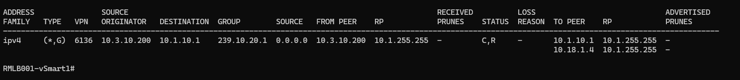
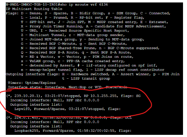
and the RP/Route-Replicator receives it and installs it correctly:

On the sender side, the stream is received by Branch 51:
But never advertised to the vSmart, so neither the RPT or the SPT can be built. I cannot explain this: my organization has the same setup, with 7 Data Centers whose routers are the RP and Route Replicator as well, using the same Multicast configurations that I am using, but I can see on their router this:
The Label Switched Path Virtual Interface is, as expected, listed in the OIL and in the Incoming interface. The only difference is that they use BSR and not static RP like I am doing.
But I don’t like copying everything millimettrically… there has to be a reason why my scenario is not working on the very last step. I can see on the debug of the RP:
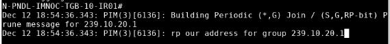
but how? If the vSmart mutlicast route originated from the PIM Join from Branch 200 is in the mRIB!
Do you have any idea?
Here are the configs for the 3 devices:
20251213_Branch51.txt (18.7 KB)
20251213_Hub.txt (23.9 KB)
20251213_Branch200.txt (11.2 KB)
I am running VRRP with 2 routers on Branch 51. Does this require any special configuration?
Thanks Laz
Ah, it was VRRP. The issue is very interesting:
On Branch 51, the BACKUP router was elected as the DR. However, the backup router was NOT receiveing the stream:
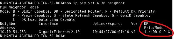
10.10.51.253 is Branch 51 R2, and here is its mRIB:
Meanwhile, R1 is NOT the DR. but is the VRRP Master router. Therefore, is the one who who gets the multicast stream (please correct me if wrong). But since is not the DR, is not going to forward nothing to the RP!!
So I ended up using a CLI Add On template and putting the 2 commands that I could not find an option for in the vManage Multicast Feature Parcel of the Service Profile of my Configuration Group:
interface GigabitEthernet2.10
vrrp 1 address-family ipv4 vrrs leader VRRP1
ip pim redundancy VRRP1 vrrp dr-priority {{PIM_DR_Priority}}
And then all worked: the Branch 51 router listed the Lspvif0 interface in the OIL:

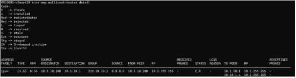
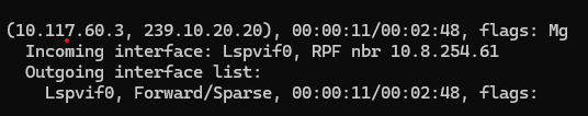
and the vSmart received the stream as an OMP Multicast route:
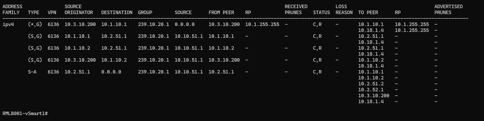
and finally the RP/Route-Replicator showed the expected output:

Thanks for your help Laz, and my apologies for not specifying the VRRP usage.
Jose
Hello Jose
Oh wow, I always get excited when someone resolves their issue and then shares the solution with us! It’s an opportunity for us to learn as well. Thank you so much for sharing this, it is really valuable information. You’ve implemented a lab with many different aspects functioning together, and understanding the way one affects the other is fundamental to correct implementation.
I was chatting with Rene, and he thought that he may, at some point, do some experimentation with SD-WAN and multicast, with your series of posts as an inspiration for this.
Thanks again, your participation is appreciated!
Laz
1 Like
Hi,
what do you mean when you say this in the lesson:
That is the case with two Internet connections like I have, but not if you have a private WAN connection (like MPLS) ?