Designing a network to support 1000 end-devices

In advance, i apologise for the long post. I’ve been assigned the task of producing a logical design for a new network that must be capable of supporting 1000 machines. The network must provide 99.9% availability and thus i must take measures to ensure capability. There must be an internet connection and provision of a reliable service is necessary. The network must support the business for a further 5 years. I am given no architectural plans of the building but there is only one building and i’m assuming one floor. The previous network had servers running Windows server 2008 R1 with domain controller there also existed a web server. I don’t think i have to be concerned with specific hardware models/names.

I have no previous experience with designing networks and I have little knowledge in the field other than a few days worth of research on the internet. I am not confident in my ability to complete the task but it is critical that i do so.

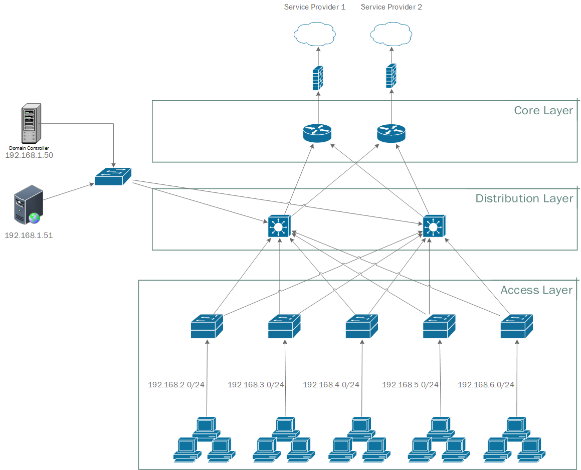
I have concluded that a hierarchical design is most fitting and that redundancy throughout each layer is necessary to comply with availability requirements. Therefore i plan to make use of multiple service providers with a partial mesh topology connecting two layer 3 switches (in the distribution layer). Then, also with partial mesh, multiple stacks of layer 2 switches in the access layer and obviously the ~1000 end devices.

I’m not sure how many stacks of layer 2 switches should exist and how they should be divided up and how or if i should subnet? I’m not entirely sure if any wireless access points are required since there is no mention of such a requirement however to be safe i imagine at least one wireless access point should be included? Are two switches sufficient to meet the 99.9% availability requirement? Where do local services, domain controller and web server, fit in such a design? Do i require some implementation of the Spanning Tree Protocol? What about firewalls, security and other software?

Thanks for reading.

Hello Sam.

It seems that you are being asked to implement a network and employ network architecture methodology. Well there’s no easy way to aquire this knowlege other than hard work and experience. However, to get you started, here’s a small crash course in network design that at least will fulfil the most important parts of your design. Let’s start with some of the excellent suggestions you have already made:

An excellent start. Let’s begin with the Internet connection and work our way in towards the internal network.

  1. Internet Connectivity and core layer
    Multiple service providers is an excellent idea. Each service provider can connect to an edge router and those two edge routers can run a gateway redundancy protocol between them. They will function as your core layer. Here you can run any routing protocols with the ISP such as BGP and you can also employ any basic access control lists and firewall functionality.
  2. Distribution Layer
    Those two routers in turn can connect to two layer 3 switches that can function as your distribution layer. This layer can provide all of your internal routing and your VLAN assignments and management. These two switches can also run a gateway redundancy protocol to provide redundancy. Each switch can be the active device for half of the VLANs while the other can be active for the other half, thus distributing the load between the two L3 switches.
  3. Access Layer
    This is the layer where end users connect to. The number of switches will depend on the number of ports per switcch which will also depend on the physical distribution of the users and the that of the structured cabling. Let’s make some assumptions.
  • 1000 users will require 1000 switch ports. Add an extra 25% in order to acomodate growth for over the next 5 years for a total of 1250 switch ports.
  • Access switches can either use stacked 48 port switches or chasis switches which take expansion cards. Either one can be used really as these two technologies are quickly converging in reliability and usage, but I am leaning a little more towards the chassis solution for two reasons: 1. saving power, fewer power supplies and internal power redundancy to the whole chassis and 2. if only two uplinks are used on stacks, there is a possibility of those switches without the uplinks to lose connectivity. Just make sure that there are two supervisor cards (the modules that have all of the inteligience, CPU, memory and so on of the device) for redundancy.
  • Assuming a high density of users, lets assume that each one of our switch stacks/chasis will be able to provide 192 ports, which is the same as 4 stacked 48 port switches or one chassis switch with four 48 port modules. This means that there will be seven such stacks/chassis for a total of 1344 ports, more than enough for what we need.
    .
    With those assumptions, each of the seven access switches will have two uplinks, one to each distribution switch for redundancy. In the case of a stack, each of these uplinks will connect to switches 1 and 2 on the stack. In the case of the chasis, two links will connect one to each supervisor card (if applicable).
  1. Now with this infrastructure set up, you need to start creating the appropriate VLANs. Having all devices in the same VLAN is not an option. Separation should occur based on some logical segregation such as department, physical location such as specific rooms or security issues. In any case, idealy there should not be more than 150 devices per subnet, but an even smaller number would be preferrable. This means that you will have to create at least 12 VLANs to acomodate the required users.

Having said all of this, you can set up the VLANs on the network however you want. What I mean is, if you have this infrastructure in place, you can assign VLANs to any port on the access layer you wish. It is preferable to group VLANs phsically as this reduces interswitch traffic on VLANs that span multiple switches, but it is not that much of an issue for the size of this network.

As for a Wi-Fi network, you can create a VLAN just for that and add access points to specific ports of switches throughout the building and have them all on the same VLAN, or multiple Wi-Fi VLANs.

Local services, domain controllers and web servers should be installed on dedicated redundant (two devices) datacentre switches that are connected directly to the L3 distribution switches. These servers should be on a dedicated VLAN and should have multiple NIC cards to connect one to each of the two datacentre switches.

Spanning tree protocol DEFINATELY must be active since you have multiple redundant layer two links. For cisco devices STP is enabled by default but can be tweaked if necessary.

Firewalls if needed should be placed between the edge routers and the L3 switches and there should be two of them to preserve the redundancy of the design.

I tried to be as concise as possible as this is indeed an extensive topic. By no means is my description the only way to go, it is however, in my opinion, a sound starting point for you to further improve your design.

I hope this has been helpful!

Laz

1 Like

I really appreciate the time and effort you put into your incredibly informative, detailed and helpful answer, thank you very much.

I have a few questions i’d like to ask and hope it’s of no bother to you to answer them.

  • What is the reasoning behind the 25% allocation for growth? Why 25%? Is there an accepted growth rate per year for a given network size or is this just guess work?
  • Why 4 access switches per stack? Is this for availability reasons? Would say 5 switches per stack be problematic (with 5 stacks) or less beneficial/efficient?
  • What are the reasons regarding the 150 device per subnet guidance? Is this related to the above question?
  • Is there any point/benefit to using more than 2 L3 switches in the distribution layer? is 2 sufficient for my scenario?
  • Why are local services, web server and the domain controller connected directly to the layer 3 switches?

There is no information given regarding physical locations or departments so I’m not really sure how to segregate appropriately with that in mind.

I apologise for the questions I just like to know the reasoning behind these things lol.

Thanks again, Sam.

Edit:
This is my attempt to design the network in visio, i’d appreciate any advice, thanks.

Hello Sam

The network is supposed to function for the next five years as is. In those five years we can expect some growth in the number of employees. Because no information was given about the expected future growth of the organization, I suggested 25% growth in order to encompass all possible growth scenarios. It was somewhat arbitrarily chosen based on my experience in corporate growth that can be expected.

This was also somewhat arbitrarily chosen. You could use 5 48 port switches for a total of 240 ports per stack. The number of switches per stack and the total number of stacks will be determined by the physical layout of the company, something you have not been given any information about. So the number is strictly arbitrary.

When you have too many devices on a network segment, you begin having problems with broadcast storms. The more devices on a single subnet the more broadcasts will take up precious bandwidth. Depending on the services being run on each segment, broadcasts may be fewer or more in number. For some applications, even 200 to 300 devices per subnet may function, however, to be on the safe side, no more than 150 devices should be placed within a subnet. Now if you’re using IPv6 this number changes as it can handle more devices per subnet. The smaller the number the better. But if the number gets too small, you have too many VLANs, administration becomes more difficult and more CPU is necessary on the distribution and core layers for routing. It’s a trade-off, a balance. With the lack of any further information to adjust these numbers more, a value of 150 was used as an absolute maximum per subnet.

Two is sufficient for the redundancy necessary. However, you may need to have more depending on the number of ports available on each and the amount of total throughput that each switch will have to maintain. Again, without additional information, this cannot be determined.

Local services are placed on datacentre switches that are directly connected to the distribution layer in order to provide a more centralized location from which all users can access them. In a sense, these services are equidistant from all of the users on the access layer, and thus are equally accessible and equally redundant.

Since there is no information about physical location, the only logical segregation is to make equally sized subnets/VLANs that are distributed evenly across the whole network.

It looks good. The only additions I would make are the following

  • provide redundancy for the server switch providing two switches and having each server connect to both switches with redundant NICs.
  • create an Active/Active redundancy between the two firewalls connecting each one to both routers.
  • the firewalls should be within the core layer
  • there should be an additional connection between the two distribution layer switches, another connection between the two core layer routers and one more connection between the two firewalls as these are necessary to allow HSRP and Active/Active firewalls to function correctly

I hope this has been helpful!

Laz

2 Likes

Very helpful. You have saved my behind! Thank you very much!

1 Like