Were can I ask a question on your site instead of replying to a message.
Anyway, my question is, do you still need DHCP snooping if your using the ‘IP helper’ command on every vlan and no workstations exist on that vlan?
Were can I ask a question on your site instead of replying to a message.
Anyway, my question is, do you still need DHCP snooping if your using the ‘IP helper’ command on every vlan and no workstations exist on that vlan?
Hello Harry
When you post a question, try to find a thread that is close to the topic that you are asking about. This is the perfect thread for this question. However, if you find that there is no thread that matches your question, you can always post a new topic, and we may re-categorize it into the appropriate thread.
As for your question, keep in mind that the IP helper address command installed on the local router will just take any DHCP request that it hears on the network and forward it to the DHCP server that exists on a different subnet. This does not prevent another rogue DHCP server on the local subnet from answering the DHCP request since this request is a broadcast and can be heard on the whole subnet. This means that you will still require DHCP snooping in order to protect yourself from rogue DHCP servers.
I hope this has been helpful!
Laz
Hi Rene ,
If there are multiple switches involved and linked up to the switch where the DHCP server is connected . In this scenario , Just curious on the command “no ip dhcp snooping information option” , do i need to apply this command across all the switches which are toward to the DHCP server ? Or just apply only the switch where the DHCP server is connected ? I believe is all the switches , am i correct ?
Hello Vilson
Yes, you are correct, if you are encountering problems with the DHCP discover message, then you must include this command no ip dhcp snooping information option on all switches through which DHCPDISCOVER, DHCPOFFER and other DHCP messages will be sent. Otherwise, the option may be added for DHCP messages traversing those particular switches causing problems for the hosts connected to them.
I hope this has been helpful!
Laz
Hi
If we have 4 vlans and 2 switches connected with trunk…do we need 4 dhcp servers to assign ips to hosts in different vlans???
Which vlan we need to put dhcp sever in ???if we want to use different pools on dhcp server???if thats possible???
Thanks lazaros…
Hello Sumant
This is a very good question. When a DHCP discover is sent, it is confined to the broadcast domain or the LAN segment of the DHCP sender. This means that if there is no DHCP server on that subnet, no one will answer.
If there were no solution to this problem, then you would indeed require a DHCP server on each subnet or VLAN. However, there is a solution to this issue, and that is the use of a DHCP relay agent. This allows there to be a single DHCP server on the network that will respond to DHCP requests from multiple VLANs, and which includes multiple pools to provide addresses from. More information about the DHCP relay agent (also known as the IP helper address configuration) can be found at the following lesson:
I hope this has been helpful!
Laz
Thanks lazaros
That means we need subinterfaces on router and put the gateway ip address (subinterface ip)for particular vlan in gidr field..and need to configure 4 different pools in dhcp server for 4 different vlans…
I hopw i am right.if now please corect me..i will try to do a lab as well..
Again thanks for your easy explanation…
Hello Sumant
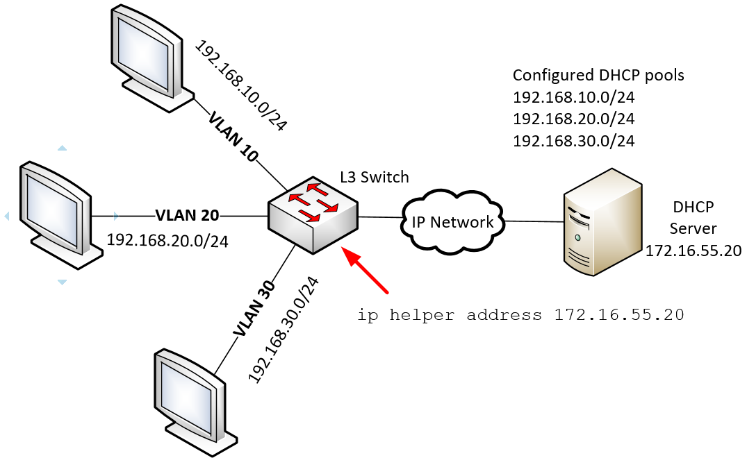
Take a look at the following diagram:
Here we have an L3 switch that has three VLANs configured on it. We want each VLAN to be assigned an IP address in the range shown, but we want to create only a single DHCP server. We have a DHCP server with an IP address of 172.16.55.20 which is completely outside of the VLANS we want to serve. In order for DHCP broadcast packets to reach this DHCP server, we configure the following command on the interface of the L3 that functions as the default gateway of EACH VLAN. So, on the VLAN 10, VLAN 20 and VLAN 30 interfaces, we enter the command ip helper address 172.16.55.20.
The result will be that any broadcast DHCP requests sent by a host on VLAN 20 for example, will reach all hosts in that VLAN including the gateway, that is, the VLAN 10 interface. This interface is configured to send such traffic in unicast form to the IP address of the DHCP server. The server receives this traffic, sees from which subnet the request is being made, and finds a free IP address within the scope that corresponds to that subnet. The response is unicast to the L3 switch, and is then broadcast to the appropriate subnet to reach the requesting host.
So you don’t need to configure subinterfaces. All you need is to ensure that the default gateway of the subnet you are configuring will have the ip helper address command to relay packets to the appropriate DHCP server.
I hope this has been helpful!
Laz
Hello everyone,
I made some complex LAB with components which lack basic features like DHCP relay.
The only possible way to relay dhcp requests was by using an GRE tunnel towards the destination DHCP server.
The tunnel was between the DHCP server and MLS (L3 Switch).
The relay agent worked great via the VTI but after adding the DHCP SNOOPING feature on the MLS, each of the remote dhcp request that came through the same DHCP vlan that I created, they have arrived to the MLS that connected to the outside network and had the VTI tunnel for relaying the dhcp request to the dhcp server via the VTI, but therefore configuring it with the DHCP SNOOPING security mechanism , suddenly the dhcp request packets stopped being relayed to the dhcp server through the VTI, only through the trusted Physical Interface that I configured, which then unfortunatly couldn’t get relayied by the next hop router because it wasn’t supporting that dhcp relaying feature.
direclty connected hosts that connected to the same MLS switch did got relayed through the tunnel, only hosts that was sitting behind another switch couldn’t cross the network via the VTI toward the DHCP server.
Is that behavior right that made the MLS stop forwarding dhcp requests through the VTI from remote hosts?
or maybe it is a bug caused by IOSv L2 Switch in GNS3?
Why couldn’t I configure the VTI itself as a trusted dhcp snooping interface as it might solve the problem?
when disabling the physical interface from being trusted toward the dhcp server, packet from direcly connected hosts still got relayed through the tunnel VTI but then the dhcp offer got blocked caused by the physical interface being an untrusted port even though the offer messages also traversed to the MLS via the tunnel.
I hope someone could help me here and search for an answer or already knows the answer.
Thanks you very much!
Hello Nitay
Hmm, if I have understood your description correctly, this is an interesting setup. It’s a good idea to try to avoid connecting a DHCP server over a tunnel, simply in order to eliminate points of failure. It would be preferable to configure the MLS to function as a DHCP server for the particular subnets it serves. Now if that’s not possible, then we would weigh the risks of setting it up as you have done.
Now, concerning DHCP snooping, you should keep the following in mind:
Now I haven’t configured DHCP snooping with a VTI, so from your comment “Why couldn’t I configure the VTI itself as a trusted dhcp snooping interface as it might solve the problem?” I assume it is not possible.
The problem you describe here shouldn’t have to do with any of the VTI configurations. If this is the case, and hosts local to the MLS are able to get their addresses, then you should check the DHCP snooping configuration of the trunk that connects the two switches. Whatever features are available to hosts directly connected to the MLS should be available to those on connected switches, if the trunking and the snooping configs are correct. I suggest you focus your troubleshooting on those connections between the switches.
I hope some of this will give you some insight into continuing your troubleshooting this problem. Keep us posted and let us know of your progress.
Laz
Thanks you very much Laz,
You understood my explanation in the right way.
Indeed when configured the other remote switches that are connected to the relay-agent MLS through trunk , they forwarded the packets to the MLS.
after that, the MLS relayed those packets through the physical interface instead through the tunnel.
I could configure the MLS as the dhcp server but it’s not right as the DHCP service provided by the another domain.
all of the switches were configured with ip dhcp snooping correctly with trust interfaces toward the main MLS that relayed the packets via the tunnel.
The MLS was configured with the same dhcp snooping while the trusted port pointing toward the dhcp server.
all of the switches configured with the command no ip dhcp snooping information option because the MLS did blocked at first the dhcp requests and logged that those packets had some problem.
I will post here my configuration on the MLS partly, and will explain what i did:
vlan 3111  //native vlan for the L2 backbone domain
   name native
vlan 10
   name DHCP
int vlan 3111
   ip address 10.1.1.1 255.0.0.0
   no shut
   ip router isis
int vlan 10
   ip address 213.57.100.2 255.255.255.0
   no shut
   ip helper-address 192.168.0.1       // dhcp server's tunnel IP

int gig0/0   // connection to unsupported dhcp relay router towards the ISP
   switchport
   sw encapsulation dot1q
   sw mode trunk
   ip dhcp snooping trust

int gig0/0.10
   encapsulation dot1q 10

int gig0/1 + gig0/2 + gig0/3    // backbone connection ports
   switchport
    sw encapsulation dot1q
    sw mode trunk
    sw trunk native vlan 3111
    mpls ip
    no shut

router isis
   is-type level-2-only
   net 49.0000.1111.1111.1111.00
   passive-interface vlan 10

mpls ldp router-id vlan 3111 force

int gig3/3   // dhcp customer port
  switchport
   sw access vlan 10
   no shut

ip dhcp snooping
ip dhcp snooping vlan 10
no ip dhcp snooping information option

int tunnel 0
   ip address 192.168.0.2 255.255.255.0
   tunnel source vlan 3111
   tunnel dest 213.57.13.254  // dhcp server's public IP


ip route 0.0.0.0 0.0.0.0 213.57.100.1   // route to the ISP's unsupported dhcp relay router only through the DHCP segment which sits on vlan 10
Hello Nitay
Hmm, that’s interesting. After doing some research I have been unable to find any information about using DHCP relay over a tunnel while implementing snooping. It may be that snooping will only be implemented on physical or VLAN interfaces, and cannot be applied to tunnel interfaces.
Is this in your GNS3 configuration? I’d like to see this implemented with real devices to see what the results would be. I wonder if @ReneMolenaar has any experience with this specific setup?
Sorry I haven’t been able to be more helpful!
Laz
Is there any problem configuring DHCP snooping and portsecurity in the same switch?
I did tests configuring on a 3560 switch but when I activated portsecurity I was not assigned IPv4 address and the port went to err-disable state
Hello Edison
DHCP snooping and port security are features that are able to function together. They do two different things, but if there is a violation in the parameters of either of the features, they can both result in an err-disabled state.
The first thing to do to troubleshoot is to determine why the port entered an err-disabled state. Is it because of the snooping or because of the port security? Once you determine that, then you will be able to determine which configuration needs adjusting to get your setup to work correctly. You can determine this by looking at the syslog messages that have been generated using the show log command. Make sure that the logging is enabled. Or you can enable the errdisable recovery feature and issue the show errdisable recovery command to see any err-disabled interfaces, and the reason for their state. You can find out more about how to determine the reasons behind the err-disable state at the following Cisco documentation:
I hope this has been helpful!
Laz
Hi All,
I’m curious if there is a documented or recommended rate limit for access ports.
With a normal windows workstation, what would the expected amount of DHCP pps that is expected on a port?
I ask because i have currently setup the majority of ports on site with a rate limit of 10.
But i have had the odd port go into err-disable due to a DHCP rate limit trigger.
i.e
UTC: %DHCP_SNOOPING-4-DHCP_SNOOPING_ERRDISABLE_WARNING: DHCP Snooping received 10 DHCP packets on interface Gi1/0/6
UTC: %DHCP_SNOOPING-4-DHCP_SNOOPING_RATE_LIMIT_EXCEEDED: The interface Gi1/0/6 is receiving more than the threshold set
UTC: %PM-4-ERR_DISABLE: dhcp-rate-limit error detected on Gi1/0/6, putting Gi1/0/6 in err-disable state
The port config is below.
interface GigabitEthernet1/0/6
 description [LAN] Access Port - Phone & PC
 switchport access vlan 210
 switchport mode access
 switchport voice vlan 66
 switchport port-security maximum 5
 switchport port-security violation restrict
 switchport port-security aging time 5
 switchport port-security aging type inactivity
 switchport port-security
 trust device cisco-phone
 storm-control broadcast level 20.00 10.00
 storm-control multicast level 30.00
 storm-control action trap
 auto qos voip cisco-phone
 spanning-tree portfast
 spanning-tree bpduguard enable
 service-policy input AutoQos-4.0-CiscoPhone-Input-Policy
 service-policy output AutoQos-4.0-Output-Policy
 ip dhcp snooping limit rate 10
end
I have seen a Cisco document that recommends it not set to more than 100, but that seems high and doesn’t really recommend a minimum threshold.
Thank you
Josh
I found an answer to my question above.
in the below link
“1Cisco recommends not configuring the untrusted interface rate limit to more than 100 packets per second. The recommended rate limit for each untrusted client is 15 packets per second. Normally, the rate limit applies to untrusted interfaces.”
Hello Josh
Thanks for sharing the answer to your question, it helps a lot!
Laz
Hi Rene and staff,
thank you for the lesson; studying them, i test your labs, but i built and test also my own labs in GNS3 (for many lessons)
So, in this case, my own lab is about DHCP snooping (so i do the post in this section), but my question is about GNS3: perhaps you will be kind to answer it
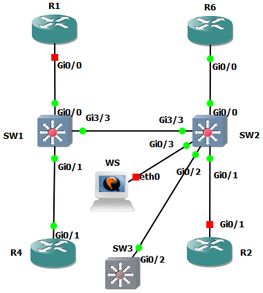
So this is the lab
When i have to config a session monitor on a SW, i use the smallest device i found for GNS3 (RAM/CPU/HD) to execute WireShark, that is Kali: perhaps this will give help for others to know that. (Is there a better solution in GNS3? i dont find a device smaller than Kali to execute WS)
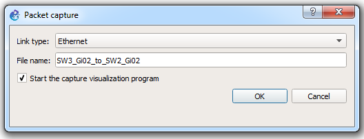
But Kali remains heavy for my GNS3 server when there are many other devices. So, for basic listening, the idea is to put another SW (in this example SW3) to capture the traffic (for example, in this lab i want to capture the traffic FROM g0/2 of SW2 TO g0/2 of SW3)
When i try the capture, i find only (traffic from SW3 TO SW2) and not (traffic from SW2 TO SW3)
So, in my lab, the capture remains always empty
Could you kindly clarify why there is just one flow direction ? which parameters are considered to determine it ? could the flow direction be reversed ?
Regards
Hello Dominique
I don’t have a clear cut answer for you as GNS3 does sometimes function strangely in certain cases, and I’m not sure if this is one of those times.
I assume that you have configured SPAN on SW2 so that you have all the traffic copied to Gi0/2 of SW2 so that SW3 can receive this traffic and capture it using the integrated Wireshark feature of GNS3. The only things I can suggest are the following:
sudo apt-get install wireshark” .Let us know how you get on with these suggestions.
I hope this has been helpful!
Laz
Hi Rene,
When I finish the DHCP config without snooping, my client is not taking an ip address. Everything is okay but it did not take an ip. Will we give ip address attacker and dhcp client interfaces?