Awesome, sounds great! This is why labbing is among the best ways to learn, because you see all of these concepts in action. And it is especially useful when you see them not working, and then you work through the reasons they’re not working until the topology works. I think that this process is the most effective learning procedure you can have for studying.
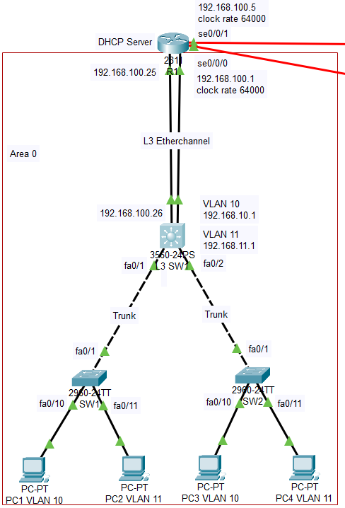
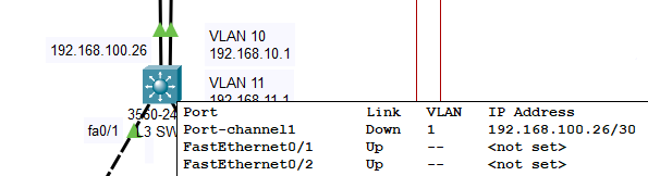
Hi Laz, I did the config on R1. I am not sure if the etherchannel is configured correctly or if I miss something, since this time its between the router and switch. The port channel link on the switch is still showing down regardless of what I try, hence no ip’s to the hosts. Please take a look, thanks.
R1
ip dhcp pool FINANCE_VLAN-10_IP-POOL-1
default-router 192.168.10.1
network 192.168.10.0 255.255.255.192
dns-server 4.2.2.2
dns-server 8.8.8.8
!
ip dhcp pool MARKETTING_VLAN-11_IP-POOL-1
default-router 192.168.11.1
network 192.168.11.0 255.255.255.192
dns-server 4.2.2.2
dns-server 8.8.8.8
!
int fa0/0
channel-group 1
no shut
exit
!
int fa0/1
channel-group 1
no shut
exit
!
!
int port-channel 1
ip address 192.168.100.25 255.255.255.252
no shut
exit
!
ip route 192.168.10.0 255.255.255.192 192.168.100.26
ip route 192.168.11.0 255.255.255.192 192.168.100.26
L3 SW1
int fa0/1
description SW1 TRUNK LINK
switchport trunk encapsulation dot1q
switchport mode trunk
switchport trunk allowed vlan all
no shut
exit
!
int fa0/2
description SW2 TRUNK LINK
switchport trunk encapsulation dot1q
switchport mode trunk
switchport trunk allowed vlan all
no shut
exit
!
!
int fa0/23
no switchport
channel-group 1 mode active
no shut
exit
!
int fa0/24
no switchport
channel-group 1 mode active
no shut
exit
!
!
int port-channel 1
ip address 192.168.100.26 255.255.255.252
no shut
exit
!
vlan 10
name FINANCE_VLAN
!
int vlan 10
ip address 192.168.10.1 255.255.255.192
exit
!
vlan 11
name MARKETTING_VLAN
!
int vlan 11
ip address 192.168.11.1 255.255.255.192
exit
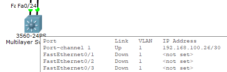
Not sure why yours is not working. I see that the ports are green on the L3 switch too. Can you ping over the therchannel?
As for your PCs not getting IP addresses, you need to have the ip-helper address command implemented on the VLAN 10 and VLAN 11 interfaces of the L3SW1 so that DHCP messages can reach R1.
Hi Laz,
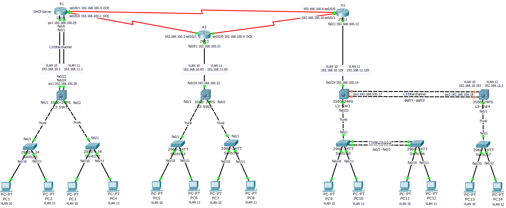
I re-configured the network in packet tracer 6.2. Everything is working ok now. The only thing is some of the PC’s take a while to get an ip, not sure why the lag. Its also bothering me that the Layer 3 etherchannel, port channel 2, between L3-SW3 & L3-SW4 is still orange. I am thinking something is malfunctioning or not configured correctly.
Great to hear that all is well! The obtaining of the DHCP addresses may be just because of the way that packet tracer works. It should actually be faster than that, but since it is working, you’re ok.
I’m not sure what to do about the amber indicators on the etherchannel. Since it is working however, I wouldn’t worry too much.
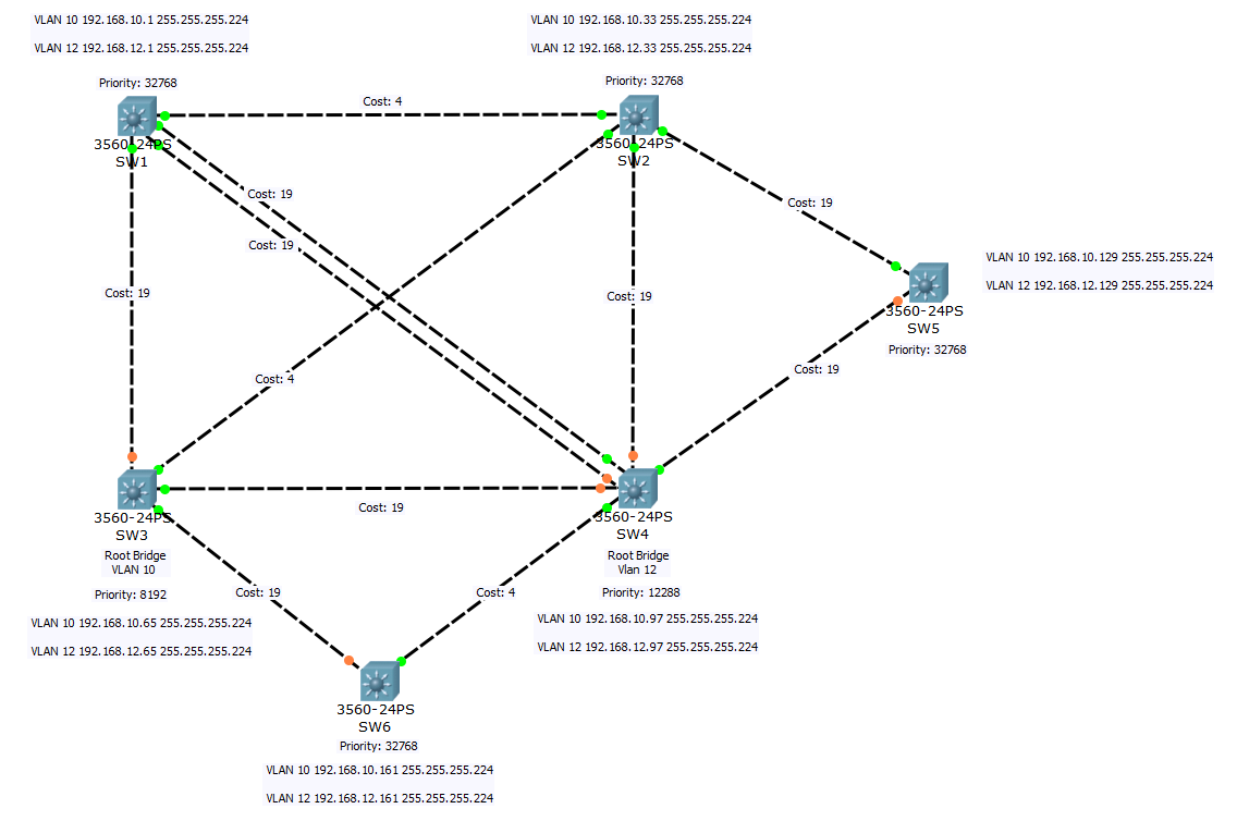
Ok thanks Laz. I am working on Spanning Tree now :). I configured a network and will change the root bridge priority, and the root port priority on the other switches to have a predefined path if possible. I configured 2 VLAN’s with ip addresses and the trunk links, ip routing is enabled as well, but I cannot ping between switches. Do I have to configure static routes, I am not sure why its not pinging, say between switch 1 and switch 2.
Also is there a command to show the mac addresses of the ports in a switch, not the mac addresses that is learned. I tried a few but to no avail, including - show version | inc base, packet tracer said invalid input at the pipe.
I see that you have put each VLAN SVI of each switch in a different subnet. In this case you will not have any layer 3 connectivity between the switches themselves, except for connectivity between VLAN10 and VLAN12 on each local switch via Inter VLAN routing.
Secondly, I assume all of the ports on all the switches are layer 2 ports (switchport and not routed) so that you can work on STP, correct? If this is the case, then IP connectivity between the switches cannot be achieved. You require some routed ports or SVIs to do this. But your VLAN 10 SVI on one switch is on a different subnet than your VLAN 10 SVI on another switch, so even if they are connected at layer 2 (trunk or access), they can’t communicate on layer three since they are on different subnets.
Having said that, if you’re looking to work on STP, then you should not involve IP addressing at all.
Focus only on the layer 2 topologies, since you don’t need to use ping to verify an STP topology.
I suggest you keep it simple by first going through some of the smaller and simpler topologies that Rene has in the Spanning Tree series of lessons, starting with this one:
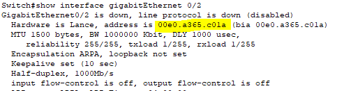
If you want to find out what the MAC address of a particular port on the switch is, you can use the show interface command. An example of the output of this command on packet tracer can be found here:
Hi Laz,
Thanks for the info. I am trying to determine the path the BPDU’s take, from the root bridge, and from the root ports. Is there a way to determine their path? I reassigned the ip’s to the switches, putting all in the same subnet, 192.168.10.1, 192.168.10.2, etc, and I can ping between the vlans on the different switches.
The command I was referring to is, if there is a command that shows all the mac addresses of the switch, all at once.
In a converged topology, BPDUs are always sent from the root bridge to all other switches. Switches will continue to propagate BPDUs throughout the topology. The only way to see this in the topology itself is using the debug commands for STP where the receipt of BPDUs is registered and displayed on the CLI.
There is no single command that i know of that lists the MAC addresses of all the interfaces. However, you can use the pipe character to filter out a command. For example, you can issue the show interfaces | include Hardware command which will show you the hardware address of all the interfaces like so:
Switch#show interfaces | include Hardware
  Hardware is Lance, address is 0090.2b8b.ee01 (bia 0090.2b8b.ee01)
  Hardware is Lance, address is 0090.2b8b.ee02 (bia 0090.2b8b.ee02)
  Hardware is Lance, address is 0090.2b8b.ee03 (bia 0090.2b8b.ee03)
...
...
...
  Hardware is Lance, address is 0090.2b8b.ee19 (bia 0090.2b8b.ee19)
  Hardware is Lance, address is 0090.2b8b.ee1a (bia 0090.2b8b.ee1a)
  Hardware is CPU Interface, address is 00e0.f96a.e0b5 (bia 00e0.f96a.e0b5)
Switch#
This will list all of the hardware addresses. You must however keep track of the order in order to determine which line corresponds with which interface.
And can you say what the wildcard mask would be for
192.168.10.64 255.255.255.192
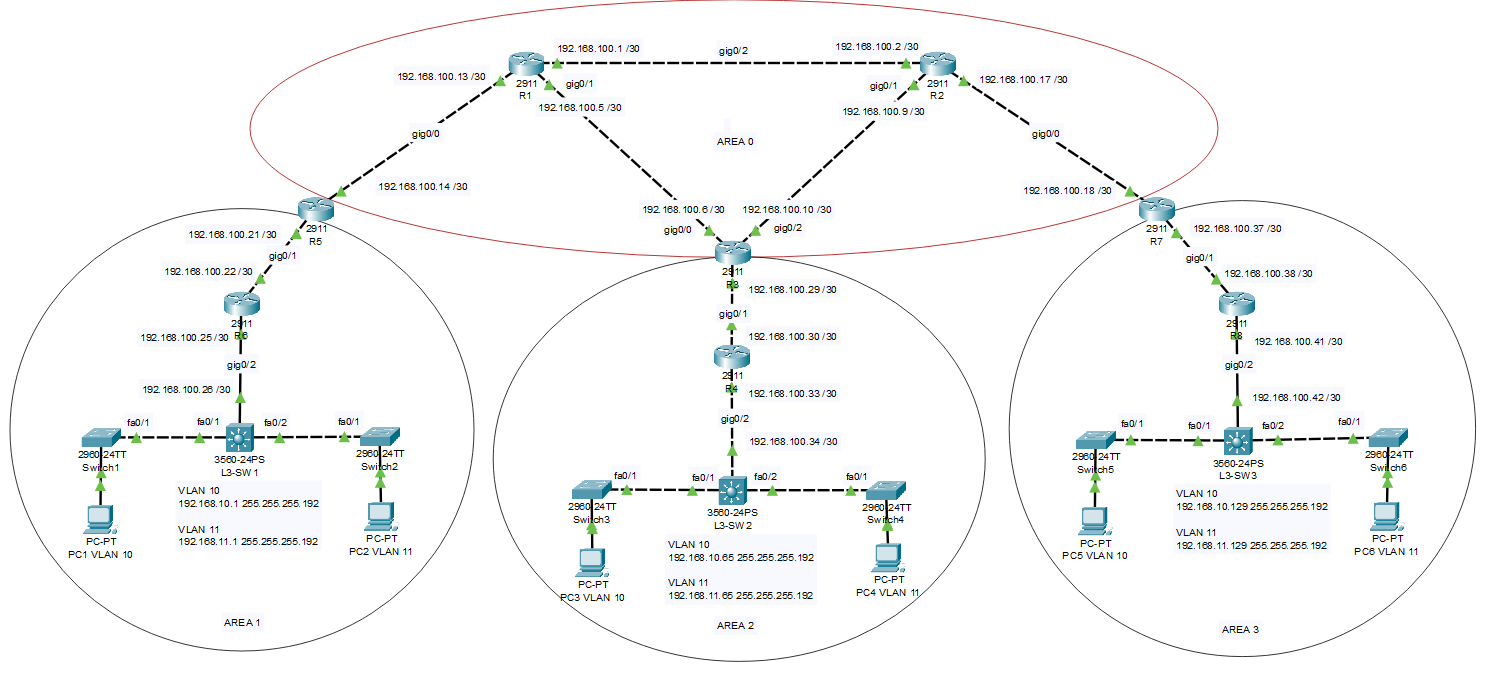
I have OSPF implemented and I can ping between routers and area 1.
In Area 2 I can ping between VLAN 10 and 11 and between routers and to Area 1, but L3-SW2 and PC not pinging to other routers, so I am thinking I have to adjust the wildcard mask
vlan 10
name FINANCE_VLAN
!
int vlan 10
ip address 192.168.10.1 255.255.255.192


vlan 11
name MARKETTING_VLAN
!
int vlan 11
ip address 192.168.11.1 255.255.255.192


int fa0/1
description SW1 TRUNK LINK
switchport trunk encapsulation dot1q
switchport mode trunk
switchport trunk allowed vlan all
no shut
exit
!
!
int fa0/2
description SW2 TRUNK LINK
switchport trunk encapsulation dot1q
switchport mode trunk
switchport trunk allowed vlan all
no shut
exit
!
!
int gig0/2
description R6 ROUTED LINK
no switchport
ip address 192.168.100.26 255.255.255.252
no shut
exit
!
!
router ospf 1
network 192.168.100.26 0.0.0.0 area 1
network 192.168.10.0 0.0.0.63 area 1
network 192.168.11.0 0.0.0.63 area 1
L3-SW2
router ospf 1
network 192.168.100.34 0.0.0.0 area 2
network 192.168.10. x xxxx area 2
If I use:
network 192.168.10.0 0.0.0.255 it works, but I am thinking you can be more specific by using the wildcard mask for the 192 subnet, like Area 1, not sure though
The wildcard mask here would be the same as the one above, since the subnet mask is the same. It would be 0.0.0.63. A cool trick you can use is if you have a subnet mask such as 255.255.255.192, take each octet and subtract it from 255. So 255-255 = 0, and 255-192 = 63. So the result is 0.0.0.63.
Or if you have a subnet mask of 255.255.252.0 for example, then the wildcard mask would be:
255-255=0
255-252=3
255-0=255
So the wildcard mask is 0.0.3.255
What you say sounds right. You should be able to use the 0.0.0.63 wildcard mask just fine. However, even the 0.0.0.255 wildcard mask will work, the result is the same. What the wildcard mask states is that any network of an interface that falls within this range of IP addresses, should participate in OSPF. So the IP address space of the VLAN 10 SVI falls within the scope of 192.168.10.0 0.0.0.255, so it will be advertised.
Hi Laz,
If I use the network commands below, on L3-SW2 in Area 2, PC 3 and PC 4 in VLAN 10 & 11 cannot ping PC 1 & 2 in Area 1, VLAN 10 & 11:
network 192.168.10.64 0.0.0.63 area 2
network 192.168.11.64 0.0.0.63 area 2
or
network 192.168.10.65 0.0.0.63 area 2
network 192.168.11.65 0.0.0.63 area 2
or
network 192.168.10.0 0.0.0.63 area 2 - This command works for L3-SW1 in area 1
network 192.168.11.0 0.0.0.63 area 2 - This command works for L3-SW1 in area 1
But if I use this network command on L3-SW2 in Area 2, PC 3 and 4 in VLAN 10 & 11 can ping PC 1 & 2 in Area 1:
network 192.168.10.0 0.0.0.255 area 2
network 192.168.11.0 0.0.0.255 area 2
Use your troubleshooting skills to take a look and see what’s happening. I suggest you test the following:
Check the subnets that are being shared on L3-SW2 and make sure the interfaces are configured with the correct IP address and especially the correct subnet mask. If the 0.0.0.63 wildcard mask doesn’t cover it, then there MUST be a discrepancy in the subnet mask.
Check that the PCs do indeed have an IP address in the correct range of addresses, and with the correct subnet.
Check the OSPF routing tables in the other routers (R3 and R4 to start with) to see what routes are being shared from L3-SW2 with both the 0.0.0.63 and the 0.0.0.255 subnet masks. This way you can see what is shared in each case, and this may give you a clue as to the cause of the problem.